Chapter 4 Combinational Logic Design Principles ( 组合逻辑设计原理 )
Digital Logic Design and Application ( 数字逻辑设计及应用 ). Chapter 4 Combinational Logic Design Principles ( 组合逻辑设计原理 ). Basic Logic Algebra ( 逻辑代数基础 ) Combinational-Circuit Analysis ( 组合电路分析 ) Combinational-Circuit Synthesis ( 组合电路综合 ).

Chapter 4 Combinational Logic Design Principles ( 组合逻辑设计原理 )
E N D
Presentation Transcript
Digital Logic Design and Application (数字逻辑设计及应用) Chapter 4 Combinational Logic Design Principles(组合逻辑设计原理) • Basic Logic Algebra • (逻辑代数基础) • Combinational-Circuit Analysis • (组合电路分析) • Combinational-Circuit Synthesis • (组合电路综合)
Digital Logic Design and Application (数字逻辑设计及应用) 第四章 组合逻辑设计原理 • 开关代数 • 公理、定理、逻辑函数的表示 • 组合电路分析 • 得到指定电路的功能(公式法化简) • 组合电路综合 • 根据命题,得到电路实现(卡诺图化简) • 定时冒险
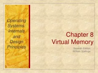
0 BC BC 4 12 8 00 01 11 10 00 01 11 10 DE DE 1 5 13 9 00 01 11 10 00 01 11 10 3 7 15 11 2 14 10 6 A = 0 A = 1 Digital Logic Design and Application (数字逻辑设计及应用) 思考:五变量如何利用卡诺图化简? 16 17 19 18 20 21 23 22 28 29 31 30 24 25 27 26
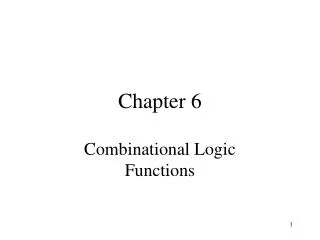
1 1 BC BC 1 1 1 00 01 11 10 00 01 11 10 DE DE 1 1 1 1 1 00 01 11 10 00 01 11 10 B·D·E’ 1 1 1 A’·C’·D 1 1 1 1 1 A·B·C’ A’·B’·D’ A·C·D’ A = 0 A = 1 Digital Logic Design and Application (数字逻辑设计及应用) F = A,B,C,D,E(0,1,2,3,4,5,10,11,14,20,21,24,25,26,27,28,29,30) F = + + + +
Digital Logic Design and Application (数字逻辑设计及应用) Chapter 6Combinational Logic Design Practices(组合逻辑设计实践) Documentation Standard and Circuit Timing (文档标准和电路定时) Commonly Used MSI Combinational Logic Device (常用的中规模组合逻辑器件)
Digital Logic Design and Application (数字逻辑设计及应用) 第6章教学大纲要求 重点学习掌握:学习利用基本的逻辑门完成规定的组合逻辑电路的设计任务:如译码器、编码器、多路选择器、多路分配器、异或门、比较器、全加器。学习利用基本的逻辑门和已有的中规模集成电路(MSI)逻辑器件如译码器、编码器、多路选择器、多路分配器、异或门、比较器、全加器、三态器件等作为设计的基本元素完成更为复杂的组合逻辑电路设计的方法。
Digital Logic Design and Application (数字逻辑设计及应用) 6.1 Documentation Standard(文档标准) Structure Thinking (结构化的理念) • Specification: Description of Interface and Function (说明书:接口及功能描述) • Block Diagram: System’s Major Function Module and their Basic Interconnections (方框图 :主要功能模块及其互联 Figure 6-1) • Schematic Diagram [原理图 (Figure 6-17)]
Digital Logic Design and Application (数字逻辑设计及应用) 6.1.1 Documentation Standard(文档标准) • Timing Diagram [定时图 (Figure 6-19)] • Structure Logic Device Description (结构化逻辑器件描述) • Circuit Description : Explains how the circuit works internally. (电路描述:解释电路内部如何工作)
& ≥1 1 Digital Logic Design and Application (数字逻辑设计及应用) 6.1.2 Gate Symbols (门的符号)
Inverter (反相器) Buffer (缓冲器) Equivalent Gate Symbols underthe Generalized Demorgan’s Theorem [等效门符号(摩根定理)]
Digital Logic Design and Application (数字逻辑设计及应用) 6.1.3 Signal Name and Active Levels (信号名和有效电平) • Name a Signal (信号的命名) • An Active Level Associated with a Signal (与信号相关的有效电平) • Active High (高电平有效) • Active Low (低电平有效) • Asserted (有效) • Deasserted(无效) • Negated(取消)
READY READY_L GO GO_L REQUEST REQUEST_L Digital Logic Design and Application (数字逻辑设计及应用) 6.1.3 Signal Name and Active Levels (信号名和有效电平) An Inversion Bubble to Indicate an Active-Low Pin (有反相圈的引脚 表示低电平有效) Given Logic Function as Occurring inside that symbolic outline. (给定逻辑功能只在符号框的内部发生) Figure 6-5,6,7,8,9,10
Digital Logic Design and Application (数字逻辑设计及应用) 6.1.5 Bubble-to-Bubble Logic Design(“圈到圈”的逻辑设计) Figure 6-11
Digital Logic Design and Application (数字逻辑设计及应用) 6.2 Circuit Timing (电路定时) Propagation Delay (传播延迟) ——A Signal Path as the Time that it takes for a Change at the Input to Produce a Change at the Output of the Path (信号通路输入端的变化引起输出端变化所需的时间) tpHL and tpLH Maybe Different Figure 6-19
Maximum Delay (最大延迟) Typical Delay (典型延迟) Minimum Delay (最小延迟) ’32 20 22 22 ’08 ’08 ’32 ’32 15 ’04 Digital Logic Design and Application (数字逻辑设计及应用) 6.2 Circuit Timing (电路定时) Propagation Delay (传播延迟) Timing Analysis: Worst-Case Delay (定时分析:取最坏情况延迟) 表 6-2 tpHL and tpLH Maybe Different
GO READY DAT READY GO DAT tDAT tDAT tRDY tRDY Digital Logic Design and Application (数字逻辑设计及应用) 6.2 Circuit Timing (电路定时) Timing Diagram [定时图(时序图)] Causality and Propagation Delay (因果性和传播延迟)
GO READY DAT READY GO DAT tRDYmin tRDYmax Digital Logic Design and Application (数字逻辑设计及应用) 6.2 Circuit Timing (电路定时) Timing Diagram [定时图(时序图)] Minimum and Maximum Delay (最小和最大延迟)
DATAOUT DATAIN WRITE_L tOUTmin tOUTmax tsetup Digital Logic Design and Application (数字逻辑设计及应用) 6.2 Circuit Timing (电路定时) Certain and Uncertain Transitions (确切的和不确切的转换)
Digital Logic Design and Application (数字逻辑设计及应用) Commonly Used MSI Combinational Logic Device(常用中规模组合逻辑器件) Encoders (编码器) Decoders (译码器) Multiplexers (多路复用器) Parity Circuits (奇偶校验) Comparators (比较器) Adders (加法器)
(输入 编码) Enable Inputs (使能输入) Map 映射 (输出 编码) Digital Logic Design and Application (数字逻辑设计及应用) Decoder and Encoder(译码器和编码器) Multiple-Input, Multiple-Output Logic Circuit (多输入、多输出电路) Enable Inputs must be Asserted to perform Normal Mapping Function (使能输入有效才能 实现正常映射功能) Input Cord Word Output Cord Word
输入 编码 输入 编码 2n中取1码 N-Bit Binary Code (n位二进制码) Map 映射 Map 映射 输出 编码 输出 编码 n位二进制码 2n中取1码 使能 使能 Digital Logic Design and Application (数字逻辑设计及应用) Most Commonly Used Case(一种最常用的情况) Decoder(译码器) Encoder(编码器) ( One-out-of 2n )
Digital Logic Design and Application (数字逻辑设计及应用) Decoder and Encoder(译码器和编码器) Decoder(译码器) Normally Output Code has More bits than its Input Code (一般来说,输出编码比输入编码位数多) Encoder(编码器) Output Code has Fewer bits than its Input Code called an Encoder (输出编码比输入编码位数少,则常称为编码器)
2-to-4 Decoder ( 2-4二进制译码器真值表 ) Outputs Y3 Y2 Y1 Y0 Inputs EN I1 I2 I0 I1 EN Y0 Y1 Y2 Y3 Digital Logic Design and Application (数字逻辑设计及应用) 6.4 Decoder(译码器) • Binary Decoder (二进制译码器) Truth Table for a 2-to-4 Binary Decoder 0 X X 0 0 0 0 1 0 0 0 0 0 1 1 0 1 0 0 1 0 1 1 0 0 1 0 0 1 1 1 1 0 0 0 Table 6-4, Figure 6-32
( 2-4二进制译码器真值表 ) Outputs Y3 Y2 Y1 Y0 Inputs EN I1 I2 0 X X 0 0 0 0 1 0 0 0 0 0 1 1 0 1 0 0 1 0 1 1 0 0 1 0 0 1 1 1 1 0 0 0 Digital Logic Design and Application (数字逻辑设计及应用) 6.4 Decoder(译码器) Truth Table for a 2-to-4 Binary Decoder Y0 = EN · ( I1’ · I2’ ) Y1 = EN · ( I1’ · I2 ) Y2 = EN · ( I1 · I2’ ) Y3 = EN · ( I1 · I2 ) Yi = EN · mi
Decoders Decoder: Popular combinational logic building block, in addition to logic gates Converts input binary number to one high output 2-input decoder: four possible input binary numbers So has four outputs, one for each possible input binary number d0 d0 d0 d0 0 1 0 0 0 d1 d1 d1 d1 0 0 1 0 0 1 1 i0 i0 i0 i0 0 0 0 0 d2 d2 d2 d2 1 1 1 0 i1 i1 i1 i1 0 1 0 d3 d3 d3 d3 0 2.9
Decoders Internal design AND gate for each output to detect input combination Decoder with enable e Outputs all 0 if e=0 Regular behavior if e=1 n-input decoder: 2n outputs d0 d0 0 0 d0 1 d1 d1 0 1 0 i0 i0 1 0 d2 d2 1 0 d1 i1 i1 1 d3 d3 e e 0 d2 0 1 d3 i1 i0 2.9 i1’i0’ i1’i0 i1i0’ i1i0
Decoder Example New Year’s Eve Countdown Display Microprocessor counts from 59 down to 0 in binary on 6-bit output 2 1 0 0 2 1 Happy 0 1 0 0 0 1 0 New Year 1 0 0 i0 d0 0 1 0 0 0 0 i1 d1 1 0 0 1 0 0 0 i2 d2 2 0 0 0 Processor 0 0 0 3 i3 d3 0 0 0 i4 i5 0 0 0 d58 0 0 0 d59 e d60 58 d61 59 d62 6x64 d63 dcd
Decoder Example Want illuminate one of 60 lights for each binary number Use 6x64 decoder 4 outputs unused 2 1 0 0 2 1 Happy 0 1 0 0 0 1 0 New Year 1 0 0 i0 d0 0 1 0 0 0 0 i1 d1 1 0 0 1 0 0 0 i2 d2 2 0 0 0 Processor 0 0 0 3 i3 d3 0 0 0 i4 i5 0 0 0 d58 0 0 0 d59 e d60 58 d61 59 d62 6x64 d63 dcd 28
I2 (3-8二进制译码器真值表) 3-to-8 Decoder Y0 Y1 I1 I2 I1 I0 Y7 Y6 Y5 Y4 Y3 Y2 Y0 Y1 I0 0 0 0 0 0 1 0 1 0 0 1 1 1 0 0 1 0 1 1 1 0 1 1 1 Y7 Digital Logic Design and Application (数字逻辑设计及应用) 6.4 Decoder(译码器) Truth Table for a 3-to- 8 Binary Decoder Yi = EN · mi 0 0 0 0 0 0 0 1 0 0 0 0 0 0 1 0 0 0 0 0 0 1 0 0 0 0 0 0 1 0 0 0 0 0 0 1 0 0 0 0 0 0 1 0 0 0 0 0 0 1 0 0 0 0 0 0 1 0 0 0 0 0 0 0 1 1 1 1 1 1 1 0 1 1 1 1 1 1 0 1 1 1 1 1 1 0 1 1 1 1 1 1 0 1 1 1 1 1 1 0 1 1 1 1 1 1 0 1 1 1 1 1 1 0 1 1 1 1 1 1 0 1 1 1 1 1 1 1
G_L 1/2 74x139 1/2 74x139 1/2 74x139 Y0_L Y1_L Y0 Y1 Y2 Y3 Y0 Y1 Y2 Y3 Y0 Y1 Y2 Y3 G A B G A B G A B Y2_L A Y3_L B Digital Logic Design and Application (数字逻辑设计及应用) Logic Symbols for Large-Scale Element (大规模元件的逻辑符号) Figure 6-36
( 1/2 74x139双2-4译码器真值表 ) 74x139 Outputs Y3_L Y2_L Y1_L Y0_L Inputs G B A The 74x139 Dual 2-to-4 Decoder(双2-4译码器74x139) Truth Table for One-half of a 74x139 Dual 2-to-4 Decoder 1 X X 1 1 1 1 0 0 0 1 1 1 0 0 0 1 1 1 0 1 0 1 0 1 0 1 1 0 1 1 0 1 1 1
G1 Select (选 择) Enable (使 能) G2A_L G2B_L Digital Logic Design and Application (数字逻辑设计及应用) The 74x138 3-to-8 Decoder(3-8译码器74x138) Y3 = G1 · G2A · G2B · C’· B · A Y3_L = Y3’ = (G1 · G2A_L’ · G2B_L’ · C’·B·A)’ =G1’ + G2A_L + G2B_L + C+B’+A’ Figure 6-34, 35
6.9 6.10 6.13 6.16 6.17 Digital Logic Design and Application (数字逻辑设计及应用) 第六章 作业
A Class Problem ( 每课一题 ) Using the information given in Table 6-2 with 74HCTxx,74AHCTxx and 74LSxx, Determine the exact maximum propagation delay from IN to OUT of the following Circuit. Compare and Comment on your results.
Digital Logic Design and Application (数字逻辑设计及应用) Chapter 6Combinational Logic Design Practices(组合逻辑设计实践) Documentation Standard and Circuit Timing (文档标准和电路定时) Commonly Used MSI Combinational Logic Device (常用的中规模组合逻辑器件)
Digital Logic Design and Application (数字逻辑设计及应用) Review of Last Class (内容回顾) 6.1 Documentation Standard (文档标准) • Signal Name and Active Level (信号名和有效电平) • Bubble-to-Bubble Logic Design (“圈到圈”逻辑设计)
Digital Logic Design and Application (数字逻辑设计及应用) Review of Last Class (内容回顾) 6.2 Circuit Timing (电路定时) • Propagation Delay (传播延迟) • Timing Analysis (定时分析) • Timing Diagram (定时图)
A B F 0 0 0 0 1 0 1 0 0 1 1 1 A A B F 0 0 0 0 1 1 1 0 1 1 1 1 A A B F F B B F Digital Logic Design and Application (数字逻辑设计及应用) Review of Last Class (内容回顾) 逻辑与:当且仅当所有输入条件都有效时,输出状态才有效。 开关状态:1-闭合、0-断开 灯的状态:1-亮 、0-不亮 F = A + B = ( A’ · B’ )’ 开关状态:0-闭合、1-断开 灯的状态:0-亮 、1-不亮
A B F Digital Logic Design and Application (数字逻辑设计及应用) Review of Last Class (内容回顾) 开关的有效状态:闭合 灯的有效状态:亮 有反相圈的引脚 表示低电平有效 给定逻辑功能只在符号框的内部发生
(输入 编码) Enable Inputs (使能输入) Map 映射 (输出 编码) Digital Logic Design and Application (数字逻辑设计及应用) Commonly Used MSI Combinational Logic Device(常用中规模组合逻辑器件) Decoders (译码器) Encoders (编码器) Multiplexers (多路复用器) Parity Circuits (奇偶校验) Comparators (比较器) Adders (加法器) Input CodeWord Output Code Word
输入 编码 n位二进制码 2-4译码器 2-4二进制译码器真值表 映射 I0 I1 EN Y0 Y1 Y2 Y3 输出 编码 输 入 EN I1 I0 输 出 Y3 Y2 Y1 Y0 2n中取1码 使能 0 X X 0 0 0 0 1 0 0 0 0 0 1 1 0 1 0 0 1 0 1 1 0 0 1 0 0 1 1 1 1 0 0 0 Digital Logic Design and Application (数字逻辑设计及应用) 6.4 Decoder(译码器) • Binary Decoder (二进制译码器) Truth Table for a 2-to-4 Binary Decoder Yi = EN · mi 当使能端有效时 Yi = mi
( 1/2 74x139双2-4译码器真值表 ) 74x139 Outputs Y3_L Y2_L Y1_L Y0_L Inputs G B A The 74x139 Dual 2-to-4 Decoder(双2-4译码器74x139) Truth Table for One-half of a 74x139 Dual 2-to-4 Decoder 1 X X 1 1 1 1 0 0 0 1 1 1 0 0 0 1 1 1 0 1 0 1 0 1 0 1 1 0 1 1 0 1 1 1
EN 74x139 Digital Logic Design and Application (数字逻辑设计及应用)
低位 高位 Y0_L EN G1 Y1_L EN G2A_L Y2_L Y3_L G2B_L Y4_L Y5_L Y6_L Y7_L Digital Logic Design and Application (数字逻辑设计及应用) EN = G1 · G2A · G2B = G1 · G2A_L’ · G2B_L’ Yi = EN · mi Yi_L = Yi’ = ( EN · mi)’
N0 N1 N2 +5V D0_L D7_L G1 G2A G2B Y0 Y7 A B C N3 U1 EN_L D8_L D15_L G1 G2A G2B Y0 Y7 A B C U2 Cascading Binary Decoders (级联二进制译码器) 用74x138设计4-16译码器 思路: 16个输出需要 片74x138? 任何时刻只有一片在工作。 4个输入中, 哪些位控制片选 哪些位控制输入
Digital Logic Design and Application (数字逻辑设计及应用) Consider: How to make a 5-to-32 Decoder with 3-to-8 Decoder? (思考:用74x138设计 5-32 译码器) How many 74x138 chips to be used with 32 outputs? (32个输出需要多少片74x138 ?) Control that only one chip works in any time (控制任何时刻只有一片工作) ——Use the Enable Inputs (利用使能端)
Digital Logic Design and Application (数字逻辑设计及应用) Consider: How to make a 5-to-32 Decoder with 3-to-8 Decoder?(思考:用74x138设计 5-32 译码器) • Control inputs of three low-order bits of a 5-bit code word (5个输入的低3位控制输入) • Control chips of two high-order bits of a 5-bit code word (5个输入的高2位控制片选) • ——Use 2-to-4 Decoder ( 利用 2-4 译码器) Figure 6-37
74x138 Y0 Y1 Y2 Y3 Y4 Y5 Y6 Y7 G1 G2A G2B A B C Digital Logic Design and Application (数字逻辑设计及应用) 补充:用译码器和逻辑门实现逻辑函数 对于二进制译码器:Yi = EN · mi 当使能端有效时,Yi = mi 对低电平有效输出:Yi_L = Yi’ 当使能端有效时,Yi_L = mi’ = Mi F = (X,Y,Z) (0,3,6,7) = (X,Y,Z) (1,2,4,5)
+5V 74x138 Y0 Y1 Y2 Y3 Y4 Y5 Y6 Y7 G1 G2A G2B F A B C Digital Logic Design and Application (数字逻辑设计及应用) 用译码器和逻辑门实现逻辑函数 当使能端有效时 Yi = mi F = (X,Y,Z) (0,3,6,7) Z Y X
+5V 74x138 Y0 Y1 Y2 Y3 Y4 Y5 Y6 Y7 G1 G2A G2B F A B C Digital Logic Design and Application (数字逻辑设计及应用) 用译码器和逻辑门实现逻辑函数 F = (X,Y,Z) (0,3,6,7) Z Y X