10 th Homework
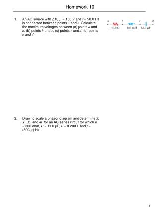
150 likes | 186 Views
Explore modeling and simulating a thread-pendulum system variation using a multi-body approach in a mechanical modeling software. Implement ElastoGap models to represent constraints and interactions accurately.

10 th Homework
E N D
Presentation Transcript
In this homework, we shall attempt the modeling of a planar mechanical system. We shall do so once by employing the planar mechanical sub-library of MultiBondLib, and once by working with a multi-bond graph directly. The version using the sub-library can be animated, whereas the direct version cannot be animated. 10th Homework
Description of the problem The ElastoGap model Planar mechanical (wrapped) thread-pendulum model Multi-bond graph (direct) thread-pendulum model
In this homework problem, we shall be dealing with modeling and simulating a thread-pendulum. A thread-pendulum is a variant of the pendulum that we have been discussing previously. Here, the mass hangs on an infinitely thin mass-less thread instead of an infinitely thin rigid bar. Consequently, the mass has now two mechanical degrees of freedom rather than one. When the mass is at an elevation higher than the origin and is moving at a velocity that is too small, it will switch to a free-fall motion that lasts until the thread is fully extended again. A Thread-Pendulum Model
The thread-pendulum can be described easily using the multi-body systems sub-library of the Modelica standard library: A Thread-Pendulum Model III
We wish to simulate the pendulum using polar coordinates. Hence we start out with a revolute joint around the inertial frame. The multi-body systems (MBS) library makes use of the state selection algorithm to get Dymola to choose the relative angle and angular velocity as two state variables. The model then proceeds with a prismatic joint, adding the second mechanical degree of freedom. The MBS library uses the state selection algorithm to convince Dymola to use the relative position and velocity of the prismatic joint as the other two state variables. Hence we operate in polar coordinates around the origin (inertial frame). A Thread-Pendulum Model IV
We still need to implement the constraint: the mass of the pendulum cannot move to a position that is farther away from the origin than the length of the thread. This constraint is tricky to implement. Let us consider for a moment a train engine impacting with a buffer-stop at a finite velocity. If the buffer-stop is infinitely rigid, the remaining kinetic energy of the train would have to be destroyed instantly, which requires an infinite force. This will either damage the locomotive, or the buffer-stop or both. Therefore, a real buffer-stop is flexible. It has a stiff spring and a damper built into the stop. A Thread-Pendulum Model V
We might be inclined to model the buffer-stop in the following fashion: The ElastoGap Model • When the train engine makes contact with the buffer-stop, the switch closes, and the spring/damper system becomes active.
Unfortunately, this approach fails. If the spring is modeled as a capacitor, then the capacitor only becomes active after contact. This means that the number of differential equations would increase by one at contact, which is something that Dymola currently doesn’t support. Remember that all switches must be placed inside algebraic loops. If the spring is modeled as a modulated effort source, the spring won’t have positional information available while the switch is open, and therefore cannot compute the spring force. The ElastoGap Model II
We wish the re-create the thread-pendulum model using the planar mechanical sub-library of MultiBondLib. Unfortunately, the 1D translational sub-library of BondLib doesn’t offer an ElastoGap model yet. Hence your first task will be to create one. Of course, you could simply use the connectors of the 1D translational sub-library of BondLib and copy the equation model over from the corresponding sub-library of the Modelica standard library. However, that would be no fun. You are supposed to create a graphical ElastoGap model. The ElastoGap Model III
In order for this to work, the spring/damper system must be continuously engaged. You cannot use a switch. One way how this task can be accomplished is by measuring not only the relative position between the two flanges, but also the force into the spring/damper system. You may then apply a pair of additional force sources at the two flanges that compensate the pair of forces (same magnitude, opposite sign) of the spring/damper system, whenever there is no contact, such that the total force at the two flanges adds up to zero. The ElastoGap Model IV
For the thread-pendulum model, we need two ElastoGap models, because in every direction there are always two constraints, i.e., two positions, where the thread is completely stretched. You are now to re-create the thread-pendulum model from elements of the planar mechanical sub-library of MultiBondLib, and the previously created ElastoGap model. You have access to the 3D mechanical model using the MBS library. You can read all of the necessary parameter values out from it. The Planar Thread-Pendulum Model
Duplicate the animated planar model and simulate it. The MBS library normalizes the angles differently from the planar library, i.e., you’ll need to modify two parameters of the model in order to avoid getting a motion that is mirrored at the vertical axis. Compare the number of equations before and after optimization obtained by the two models as well as their execution efficiencies. The Planar Thread-Pendulum Model II
You are now supposed to create a third model of the thread-pendulum, this time using a direct multi-bond graph approach, i.e., without wrapping. You may formulate the two constraints in the equation window, i.e., you don’t need to create a direct bond-graph version of the ElastoGap model. This model cannot be animated. Plot the vertical motion of the pendulum mass against its horizontal motion. Compare the number of equations and execution speed with the previous two solutions. The Multi-bond Graph Thread-Pendulum Model