Download
1 / 16
160 likes | 179 Views
Extract key insights from a presentation outlining the Interaction Region requirements for the EIC Accelerator Collaboration. Focus on FFQ parameters, dynamic aperture, multipole analysis, corrector schemes, and magnet data extrapolation.

E N D
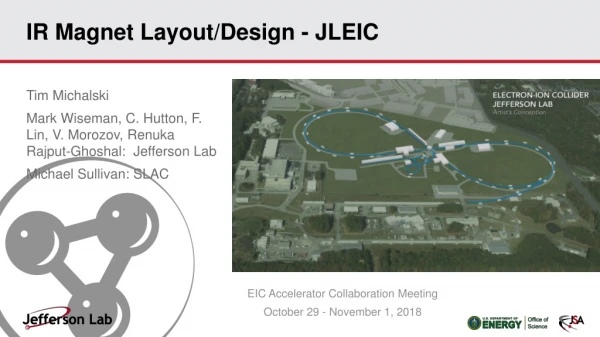
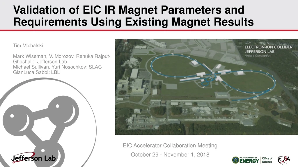
Validation of EIC IR Magnet Parameters and Requirements Using Existing Magnet Results Tim Michalski Mark Wiseman, V. Morozov, Renuka Rajput-Ghoshal : Jefferson Lab Michael Sullivan, Yuri Nosochkov: SLAC GianLuca Sabbi: LBL EIC Accelerator Collaboration Meeting October 29 - November 1, 2018
Presentation Outline • Overview of Interaction Region Requirements • Interaction Region Layout Overview • FFQ Parameters – Detector Acceptance • Dynamic Aperture • Multipole Analysis • Corrector Schemes • Extrapolation of Existing Magnet Data – Beam Dynamics Aspects • Extrapolation of Existing Magnet Data – Engineering Aspects • Heat and Radiation Loads on IR Magnets • Timetable of Activities • Summary Fall 2018 EIC Accelerator Collaboration Meeting
Overview of the Interaction Region Requirements • To maximize the luminosity, the FFQs should be placed as close to the interaction point (IP) as possible. • The optical functions grow quadratically with the distance from the IP: • Reaching high luminosity requires strong focusing and therefore small . • With of a few cm, the functions may reach large values by the entrance of the first FFQ. Beam optics of the ion detector region. Fall 2018 EIC Accelerator Collaboration Meeting
Overview of the Interaction Region Requirements • With the minimum necessary detector space of 7 m downstream of the IP, the functions reach maximum values of about 2500 m inside the downstream ion FFQs. • The beam is very sensitive to magnet misalignments and multipole components in the IR. • It is very important to: • Understand the alignment and multipole requirements of the FFQs • To design an orbit correction scheme and a multipole compensation system • Shorter FFQ focal length, preferable from the beam dynamics point of view, requires higher FFQ gradients • In combination with the large aperture requirement, this leads to high maximum magnetic fields on the FFQ conductor Typical parameters of the downstream ion FFQs for JLEIC. The magnetic field values are shown for 100 GeV/c protons. The distance from the IP is the distance from the IP to the magnet face oriented towards the IP. Rinner≡Bpole-tip/(∂By/∂x) Fall 2018 EIC Accelerator Collaboration Meeting
Interaction Region Layout Overview • The design thus far considered six distinct areas of magnets • Detector Solenoid ( 4 m) • SB1 dipole (1.5 m) • SB2 dipole (~4.6 m) • Ion entrant side cryostat (~8.7 m) • Electron entrant cryostat, between the Detector Solenoid and SB1 (~2.6 m) • Ion down beam cryostat between the two spectrometer dipoles (~10.4 m) ~32 m i e 3 4 5 6 2 1 Fall 2018 EIC Accelerator Collaboration Meeting
FFQ Parameters – Detector Acceptance • Downstream ion FFQ parameters are driven by forward detection considerations • Desire a clear line of sight from the IP through the FFQ apertures within a cone of about 20 mrad • Forward acceptance to charged particles studied using GEANT4 for multiple protons originating at the IP with different initial angles and rigidity offsets with respect to the nominal proton beam. • All particles that go outside the apertures anywhere inside the quads are considered lost. Fall 2018 EIC Accelerator Collaboration Meeting
FFQ Parameters – Detector Acceptance • Simulation of neutral particles for 6, 9, and 12 T FFQ pole-tip fields • The transmitted particles are indicated in blue. The black circle outlines cone. • Adequate acceptance to neutral particles. • Higher acceptance is more preferable for nuclear physics experiments. Fall 2018 EIC Accelerator Collaboration Meeting
Dynamic Aperture • Multipole components limit dynamic aperture (DA) • A dynamic aperture was simulated including imperfections, corrections, and beam-beam interaction effects should be of the order of • Making the DA significantly less reduces the beam lifetime and causes luminosity loss • Dominant effect comes from the magnets located in areas with large function values • In a collider, the largest functions occur inside FFQs Fall 2018 EIC Accelerator Collaboration Meeting
Multipole Initial Analysis • The limiting multipole strengths serve as multipole tolerances for magnet designers. • This analysis is very preliminary. • Requires further assessment of: • Misalignments • Orbit correction • Multipole correction • Beam-beam interaction Fall 2018 EIC Accelerator Collaboration Meeting
Corrector Schemes • Design of the orbit correction scheme in the IR • Integration of orbit correctors and diagnostics • Tolerances on the alignment of elements • Specification of orbit corrector and diagnostics requirements • Design of the multipole correction scheme in the IR • Integration of multipole correctors • Specification of multipole field without multipole correction • Simulation of local compensation of magnet multipoles • Specification of multipole field after compensation • Specification of multipole corrector strength and alignment requirements • Impact of coil end multipoles and their compensation • Space requirements including coil ends, cryostats, orbit and multipole correctors, and diagnostics • Identification of key magnet parameters to verify using existing magnet data and to test by prototyping Fall 2018 EIC Accelerator Collaboration Meeting
Extrapolation of Existing Magnet Data – Beam Dynamics Aspects • Multipole strengths can be scaled in terms of the reference radius , magnet coil radius , and function value at the magnet as: • Equation (3) preserves the contributions of the magnet multipole components to the resonance driving terms • Tasks to be completed: • Scaling of existing magnet data to EIC magnet requirements • Determination of EIC performance assuming demonstrated magnet parameters • Identification of limiting magnet parameters and of critical magnet R&D to improve them • Comparison of EIC magnet requirements with BNL prototype test results when they become available Fall 2018 EIC Accelerator Collaboration Meeting
Extrapolation of Existing Magnet Data – Engineering Aspects • Design challenges stated in IR Magnet Layout/Design – JLEIC presentation • Iterate and optimize on the key parameters (coil radius, gradient and magnetic length) • The main reference – LHC accelerator research program (LARP) in support of the HL-LHC • JLEIC, in comparison to HL-LHC, has larger aperture and close proximity to electron beamline • Tasks to be completed: • Exploration of alternative conductor technologies • Assess how LARP HL-LHC FFQs translates to the JLEIC IR FFQ magnets • Comparison of alternative mechanical structure designs - LARP FFQ, BNL High Gradient Shielded Quadrupole • Analysis of field quality that can be achieved in Nb3Sn Fall 2018 EIC Accelerator Collaboration Meeting
Heat and Radiation Loads on IR Magnets • For each FFQ change, modeling of the SR backgrounds must be reassessed • The next step is modeling secondary scattering from beam pipe surfaces / mask tips i e 160 cm 240 cm Interaction point Fall 2018 EIC Accelerator Collaboration Meeting
Timetable of Activities Fall 2018 EIC Accelerator Collaboration Meeting
Summary • Development of a sound IR design is necessary for a successful EIC • An initial JLEIC design has been completed as part of the FY’17 Base R&D • The design of the electron IR corrector scheme is nearly complete • A plan for assessing specifications and their effects has been developed Fall 2018 EIC Accelerator Collaboration Meeting
Thank you for your attention. Are there any questions? Fall 2018 EIC Accelerator Collaboration Meeting