Download

1 / 9
90 likes | 103 Views
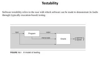
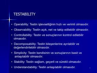
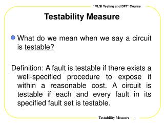
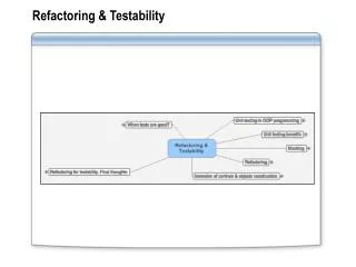
This detailed technical document discusses the functional descriptions and testability of the Mimosa22 pixel array with rolling shutter readout. It covers various operational modes, synchronization modes, test modes, and implementation details.

E N D
Functional descriptions • 576 x (128 + 8) array of 18.4 µm pixel • Two groups of design (IPHC / DAPNIA) • In pixel CDS (1 pixel readout = 16 CK cycles, next slide) • With Standard diodes & RadTol diodes • 128 discriminators at bottom of the matrix • Need 2 stable reference voltage thresholds (accuracy ~1 mV) provided by the bias DAC on chip • Backup solution: external references • Rolling shutter readout • Digital: • 8 to 1 at a frequency up to 50 MHz, 16 output pads • Analogue: • 8 output pads (output simultaneously with digital outputs) • Matrix steering logic (width ~300 µm) • Should be less with 30 µm pitch pixels • On the left hand side of the matrix • Bias reference sources + JTAG controller Mi22=>Phase1 christine.hu@ires.in2p3.fr
Pixel Mimosa22 = Pixel MimoStar3 • CDS in pixel needs 16 clock cycles 1 5 10 15 16 CK RowSlct Read Rst Clamping Calib Latch Digital CK • Discriminator compares the difference pixel output levels during the Read & Calib phases with threshold voltages • If LevelRead = LevelCalib, Output Discri = 0 • If LevelRead > LevelCalib+ Levelthreshold, Output Discri = 1 • Yield of pixel array ? • MimoSTAR3 values cannot be simply extrapolated Mi22=>Phase1 christine.hu@ires.in2p3.fr
Testability same for Phase1? • Mimosa22 is driven by an external clock at 100 MHz. A 50 MHz clock is generated by Mimosa22 and sent to the DAQ to sample digital data. Markers are also provided by Mimosa22 for DAQ synchronization • Two Operational Modes: • OpM1: 576 lines only the pixel array is read • OpM2: 578 lines the pixel array is read followed by a 128 bit pattern read twice (preset or JTAG loaded) • Two Synchronization Modes: Mimosa22 provides a continuous clock in both modes • Sync1: On DAQ request, Mimosa22 provides markers on last pixels both for analog and digital outputs • Sync2: On DAQ request, Mimosa22 generates a clock which starts on the first pixel of the frame Mi22=>Phase1 christine.hu@ires.in2p3.fr
Testability (cont.) • Two Test Modes: • Discriminator test mode: • 2 levels emulate the signals generated on Read & CALIB phases by the pixels • Implemented by 2 programmable analogue signals connected to the discriminator inputs • Data transfer mode: • A 128 bit pattern is sent continuously • Markers are maintained • External START signal for an N chip ladder synchronization • Phase1 issue: 10 chips to synchronize with a 160 MHz clock? • Possibility to disable the latch output of discriminators individually (JTAG) • Implementation of a simple temperature sensor Mi22=>Phase1 christine.hu@ires.in2p3.fr
Phase 1 Floor-plan Selectable analog outputs (Max: 1/5) ~ 200 µm for Pads + Electronics Shift Row Reg 640bits Pixel array 640x640 Pixel sequencer + Buffer tree FRDO / 10 (16 CK) 640 Discriminators FRDO / 160 Disable discriminator Register 160 to 1 Simple digital pattern generator for data transfer test purpose FRDO / 4 401 401 401 401 401 401 401 401 401 401 401 401 401 401 401 401 FRDO MUX41 LVDS MUX 41 LVDS MUX41 LVDS MUX 41 LVDS Integration time = 160 / FRDO x 640 • Ex. FRDO = 160 MHz • Discriminator freq. = 1 MHz, In pixel freq. = 16 MHz Integration time = 640 µs • Phase 1 driven by an external clock at FRDO Mi22=>Phase1 christine.hu@ires.in2p3.fr
Phase 1 • Are the testabilities implemented in Mimosa22 sufficient enough? • What about chips synchronization at the ladder level? • Do we accept de-synchronization of few pixels /chip? • Control bus is common (in parallel for N chips) • Data transfer bus • 4 LVDS outputs x 10 = 80 lines • + 1 clock and 1 marker per chip = 40 lines • How to ensure data acquisition at 160 MHz? (No experience at IPHC) Mi22=>Phase1 christine.hu@ires.in2p3.fr
1 5 10 15 16 CK RowSlct Read Rst Clamping Calib Latch 1 5 10 16 1 5 10 16 1 5 10 16 1 5 10 Mi22=>Phase1 christine.hu@ires.in2p3.fr