Download
1 / 34
350 likes | 523 Views
Explore power flow, losses, and wave propagation in rectangular and cylindrical waveguides with TE10 mode. Study phase mixing, amplitude modulation, and dispersion with a transmission analogy. Design a rectangular waveguide for optimal TE10 wave propagation and minimize cutoff frequency. Compare field distributions in cylindrical waveguides. Understand loss mechanisms and implications of waveguide dimensions and materials.

E N D
rectangular waveguide TE power flow losses cylindrical waveguide 10
y b Ey 0 x a z 0 0 z a x rectangular waveguides TE10 mode
y b 0 x a z 0 y b 0 x a z 0 y b 0 x a z 0 rectangular waveguides TE10 mode a = 2b
y b 0 x a z 0 rectangular waveguides TE10 mode a = 3 cm
y b 0 x a b z 0 wc w rectangular waveguides TE10 mode
y b 0 x a z 0 rectangular waveguides TE10 mode
y b 0 x a z 0 rectangular waveguides TE10 mode
y b Ey 0 x a z 0 0 z g a x rectangular waveguides TE10 mode
y b 0 x a z 0 rectangular waveguides TE10 mode
b wc w Movie to illustrate phase mixing of two propagating sinewaves in a dispersive media.
Movie to illustrate the propagation of an amplitude modulated pulse in a waveguide
t1 t1 t1 z z z t2 t2 t2 z z z t3 t3 t3 z z z dispersion
t1 z t2 z t3 z dispersion
y b 0 x a z 0 rectangular waveguides TE10 mode 8.8.e. The transmission analogy can be applied to the transverse field components, the ratios of which are constants over guide cross sections and are given by wave impedances. A rectangular waveguide of inside dimensions [a = 4, b = 2 cm] is to propagate a TE10 mode of frequency 5 GHz. A dielectric of constant r=3 fills the guide for z>0 with an air dielectric for z<o.
y b 0 x a z 0 rectangular waveguides TE10 mode
y b 0 x a z 0 rectangular waveguides TE10 mode
y lossy dielectric b 0 x a z 0 rectangular waveguides TE10 mode The wave will attenuate as it propagates.
y b 0 x a z 0 rectangular waveguides TE10 mode Loss in walls due to finite conductivity of metal surfaces Tangential H surface current js Ohmic power loss Attenuation of the em wave
matching y b Ey 0 x a z 0 0 z a x rectangular waveguides TE10 mode
y b 0 x a z 0 rectangular waveguides 8.8a. For f=3 GHz, design a rectangular waveguide with copper conductor and air dielectric so that the TE10 wave will propagate with a 30% safety factor (f = 1.30fc) but also so that wave type with next higher cutoff will be 30% below its cutoff frequency. a = 6.5 cm b = 3.85 cm
cylindrical waveguide
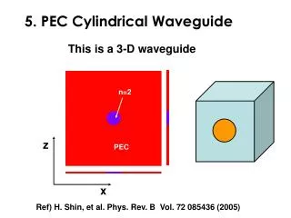
a j z Cylindrical Waveguides
a j z Cylindrical Waveguides Bessel function
1 J0(x) J1(x) 0 0 10 20
a j z 1 J0(x) J1(x) 0 0 10 20 Cylindrical Waveguides n is angular variation l is radial variation
a j z Cylindrical Waveguides
a j z 1 J0(x) J1(x) 0 0 10 20 Cylindrical Waveguides n is angular variation l is radial variation
Loss decreases as frequency increases Field distribution is similar to TE10 mode in rectangular waveguide
v a c j v z 1 vg wc w