Download
1 / 26
260 likes | 292 Views
Solar Powered FDM 3D Printer. P18462. Team Members. From left to right:. Agenda.

E N D
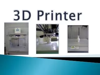
Solar Powered FDM 3D Printer P18462
Team Members From left to right:
Agenda Problem Statement Recap………………………………………………………………………………………………………………4Supplies…………………………………………………………………………………………………………...…………………………..5-8Feasibility Calculations……………………………………………………………………………………………………………………9Design 2 Overview ………………………………………………………………………………………………………………………..10 Design 2 Subsystems…………………………………………………………………………………………………..………..……...11Electrical Schematic Design 2 …………………………………………………………………………………………………10-16Bill of Materials………...…………………………………………………………………………………………………………………....17Battery Weight vs Capacity/Time………..……………………………………………………………………………………18-19Test Plan………………………………………………………………………………………………………………………..…………20-22 Risk Assessment……………………………………………………………………………………………………………………………23Goals for MSD II…………………………………………………………………………………………………………….……………...24Timeline for MSD II………………………………………….…………………………………………………………….……………...25
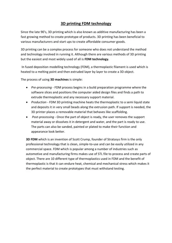
Problem Statement Key Deliverables • Modify power systems in a 3D Printer to function in Colombia • Grid power not reliable • Possible use case • Skills Trading • Goods Production • Wheel out to customer • A prototype and tested design of a solar-powered 3D printer • Documents pertaining to the development and design of the product • Troubleshooting guide to allow customers/operators to service and maintain printer
Supplies • Supplies from old MSD team • Supplies include: • Battery (75 amp/h) • 2 x solar panel (100 W) • MPPT controller
Supplies - Battery • Duracell Ultra Deep Cycle • 75 amp/h • Can successfully hold a charge and power
Supplies - Solar Panel • 2 x GrapeSolar Photovoltaic Modules • Max Peak Power = 100W • Max Power Point Voltage = 18V • Max Power Point Current = 5.56A
Supplies - MPPT Solar Charge Controller • Helps regulate solar power coming in • Has ports for PV and Battery power
Feasibility Calculations Component Power Consumption (from testing) • Printer: 60 W average • Laptop: 50 W Assuming: 90% efficiency for MPPT module and DC-AC converter 4 hours of optimal solar charging time Laptop will not regularly run on system after print starts Battery Capacity Desired Solar Panel Output 60 W 60 AH
Design Overview 2 Laptop Grid Power Maximum Power Point Tracker Controller (MPPT) Solar Power Printer Arduino Mega Battery
Design 2 Subsystems Main Electrical Subsystems: • Switching Circuit - needed to automatically control which power source should be used • Powering Arduino - Arduino must always be running • Temperature Sensor - used as safety precaution for battery overheating • Battery Charging - battery needs to be constantly charged or charging in case other sources are not available
Electrical Schematic - Design 2 • MPPT module requires constant battery connection. • Current flow to and from the battery is monitored as well as battery voltage • The transistor circuitry controls the current flow from the AC source • The Arduino controls the transistor to balance power needs with solar power
Design 2 changes from PDDR to DDR • Relays were replaced with transistors to perform the needed switching. This removes the need for digital logic coding conducted by the Arduino and allows for analog current control. • Added Op Amps to monitor current throughout the systems • Added capacitor in between the printer and AC to DC loads to increase protection by delaying quick voltage changes due to switching • From testing our acquired parts, we learned that the MPPT controller needs to always be connected to the battery to function properly
Battery Weight vs Capacity/Time • Use Time Before Dying was determined using the equation in the Feasibility Calculations Slide (9) • Laptop Power was considered in the calculations to show the the approximate amount of time the battery will run with the highest possible power consumption value
Battery Weight vs Capacity/Time Graph Focus here for ideal weight and time
Preliminary Test Plan What we won’t test: • ER #1: Print Volume • ER #2: Print Speed • ER #6: Print Resolution • ER #8: Filament Diameter What we’ll test: • ER #4: Wattage/Power Consumption • ER #9: Assembly Time • ER #10: Operation Start-up Time • ER #11: Intervention rate • Maintenance/diagnostics • Components function • Packaging effectiveness Important things to watch: • ER #3: Device Size • ER #5: Cost • ER #7: Weight
Preliminary Test Plan - cont. Responsibilities will be assigned and refined once our schedules are known for next semester.
MSD II Goals • Build switching system circuit • Improve durability • Improve portability • Implement packaging • Create Repair Manual • Reduce user intervention • Implement solution to allow print to “fail gracefully” • Debug and test • Complete needed Deliverables