Download
1 / 12
120 likes | 206 Views
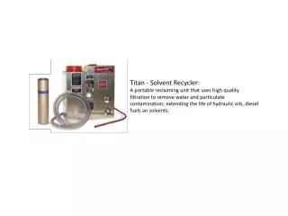
Designed by Zack, Travis, Dana, and team, this project focuses on detailed design and construction of the K-Cup recycling process, with a unique lid/no lid sensor, heat and punch component, and vacuum system.

E N D
K-Cup Recycler Zack Burchman Travis Gang Dana Geer Ryan Neary Matt Seekins Faculty Advisor: Mike Rosen GMCR Contacts: Wade Hodge Paul Comey Jason King
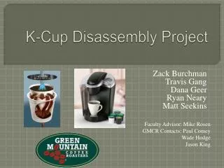
Direction for the Project Designed the foundation for entire K-Cup recycling process Focus on detailed design and construction of foil weld and coffee ground removal sub-systems
Charter Statement • Lid/No Lid Sensor • Heat and Punch Component • Will break foil weld • Fully automated • Vacuum • Will remove foil and grounds • Fully automated
Heat & Punch Design Heating element custom made by Watlow Electric Manufacturing Company Pneumatic pistons will drive motion Cup is raised to contact heating element, lowered, then punch lowers to break weld
Vacuum Design Current vacuums in use
Proposed Schedule • Winter Break: Team members research and design designated parts • We will conduct compatibility checks and purchase parts throughout January • February • Dana begins work on building the vacuum and cup holder • Travis and Zack begin building the riser system, and later start the punch • Matt will test the sensors and power supply while designing the control system • Everyone is helping design and purchase the framework
Proposed Schedule • March • Dana begins to test on the cup holder and will finish the vacuum and begin to troubleshoot it • Travis and Zack start the heating element and continue building the punch, testing begins on the riser and later on the punch and heating element • Matt begins to integrate the control system, sensors, and power supply to the machine • The framework building begins
Proposed Schedule • April • Everything is built and each individual parts are tested and debugged • It is all put together and debugged
PERT Chart Heating System Critical Path: 14 weeks 4 Punching System 3 2 4 Test Subsystems Design Heat/Punch 1 1 Power Supply 2 4 3 1 Assembled Machine Test Machine Start 1 2 4 Design Vacuum Design Framework Build Framework 2 3 2 1 4 3 Control subsystems Integrate Control Subsystems 3 1 Sensors 2 Vacuum System
Cup is placed into die A force is applied to the punch Punch comes down slicing off ring Cup falls down through the die and moves on to next stage for sorting The ring, which remains on top of the die, is blow off into a waste compartment Adaptable to any system 3 steel rods, bearings, springs
Questions? Thanks to GMCR for coming out!