Download
1 / 12
120 likes | 283 Views
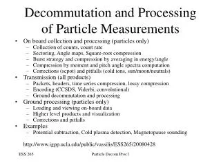
Particle Measurements. Types of particle measurements Langmuir Probes Retarding potential analyzers Magnetic spectrographs Energetic neutral atom imagers Electrostatic analyzers http://www.igpp.ucla.edu/public/vassilis/ESS265/20080421. Langmuir Probes, Overview.

E N D
Particle Measurements • Types of particle measurements • Langmuir Probes • Retarding potential analyzers • Magnetic spectrographs • Energetic neutral atom imagers • Electrostatic analyzers http://www.igpp.ucla.edu/public/vassilis/ESS265/20080421 Low Energy Particle Instruments 1
Langmuir Probes, Overview • In the ionosphere, where lD is ~1-10cm (Ti, Te ~eV, Ne~ 102-106) • Scan in voltage, get Ni, Te, Ne • Boom away from spacecraft body, normal to flow • Need to ensure sensor is small relative to ion gyroradius • Missions: AE, DE-2, AE-C, PVO Low Energy Particle Instruments 2
Langmuir Probes, Issues • Non exponential fit reveals issues to deal with: • Cleanliness: Spacecraft conductive to avoid charging • Surface materials clean (Oxygen bombardment causes permanent non conductive layer, asymmetry of sensor) • Avoid by heating up to outgass early in the mission • Avoid by allowing thermal (high energy) electrons to bombard surface • High altitude missions do not have this problem • Work function patchiness low • Order of 100mV is too high (corresponds to 1160K) for E-region temperatures of 300K (0.03eV) • Use vitreous carbon (Weismann & Kintner 1963 on rockets) or highly oriented metals (PVO: rhenium, molybdenum) • Minimize VxB in high fields • Venus, Mars OK (low fields) but at Earth, cross field antenna motion causes E along boom • Minimize by tipping boom along B • Further reading: • Brace, L. H., Langmuir probe measurements in the ionosphere, in Measurement Techniques in Space Plasmas: Particles, Geophys. Monogr. Ser. 102, AGU, 1998 • Krehbiel, J. P., et al., The DE Langmuir probe instrument, Space Sci. Instrumentation, 5, 493, 1981. • Mott-Smith, J. M. and I. Langmuir, The theory of collectors in gaseous discharges, Phys. Rev., 28, 727, 1926. Low Energy Particle Instruments 3
Retarding Potential Analyzers • In the ionosphere, mount along ram velocity, measure species densities • Ram speed (7.5km/s) is high or supersonic relative to ion thermal speed or motion • Spacecraft charging is negative and small relative to motional energy • I-V curve has steps at qVret = ½m(Vsr+Vr)2 – qys ; where: ys = sensor potential relative to plasma, Vsr= ram speed • Homework #1 Show that the thermal width of the steps is m Vsr Vth, where Vth is the ion species thermal speed. Show that for sensor potential of –0.8V, the step functions are at 1.1V for H+ and 6V for O+. • Ions can be further differentiated with mass spectrograph behind RPA • See: Chappell et al., The retarding ion mass spectrometer on DE-1, Space Sci. Instr. 4, 477, 1981 Heelis and Hanson, 1998 Low Energy Particle Instruments 4
RPA/Ion Drift Meters • In the ionosphere, mounted along ram velocity, measure species velocity • G2 retards lower energy H+, but allows higher energy O+ through • Collimated beam comes through and falls asymmetrically on collectors • G6 suppresses electrons, G3-5 are grounded to remove distortions • Homework #2: Determine transverse velocity Vt as function of ram speed, W, D. • Issues: Vt error can be significant when ram direction angle is large • Further reading: • Heelis and Hanson, Measurements of Thermal Ion Drift Velocity and TemperatureUsing Planar Sensors, in Measurement Techniques in Space Plasmas: Particles,Geophys. Monogr. Ser. 102, AGU, 1998 Heelis and Hanson, 1998 Low Energy Particle Instruments 5
RPAs in tenuous plasmas • In the solar wind, rely on supersonic motion • G1, G3 are shields (ground); G4 is suppressor (-200V) • G3 is modulator between V1-V2, resulting in dif. Current • North-South RPA measurement results in transverse speed • Spinning (2.7sec) results in azimuth sectors (11.25o, 45o) • Scanning in velocity/energy results in temperature • Full scan (11V-1.3 kV) initially • tracking mode after lock on Vram allows data compression • Further reading: • Lazarus and Paulanera, A comparison of solar wind parameters from experiments on the IMP8 and WIND spacecraft, in Measurement Techniques in Space Plasmas: Particles, Geophys. Monogr. Ser. 102, AGU, 1998 Low Energy Particle Instruments 6 Lazarus and Paulanera, 1998
Magnetic Spectrographs • For low energy particles (left): • post-acceleration Vpa behind an RPA provides V, T and m/q • Homework #3 Show that in LIMS: m/q=(Brc)2/(2Vpa), where B is magnetic field, rc magnet curvature • For higher energy particles (right): • Broom magnet clears electrons • High field bends high energy ions • Ions that were not bent assumed neutrals (ENAs) • Further reading: • Reasoner et al., Light ion mass spectrometer for space-plasma investigations: Rev. Sci. Instr. 53(4), p. 441, 1982. LIMS Magnetic Spectrograph on CRRES Low Energy Particle Instruments 7
Electrostatic Analyzers • Electrostatic deflection analyzes velocity distribution • Analyzer constant, K=R1/D, where D=R2-R1; Outer shell is at 0 Volts, inner shell at potential V. • Electrostatic deflection at entrance aperture can measure incoming ions from different directions if spacecraft non-spinning • Homework #4 Show that the energy E of the particles of charge q, incident on the MCP is E=-K q V /2 • Further reading: • Carlson et al., The electron and ion plasma experiment for FAST: Space Sci. Rev. 98, 33, 2001. • McFadden et al., The THEMIS ESA plasma instrument and in-flight calibration, Space Sci. Rev., in press Low Energy Particle Instruments 8
Time of Flight • Electrostatic deflection => energy per charge: E/Q. Time of flight, t, => energy per mass E/M • Post-acceleration UACC provides sufficient energy for optimal McP operation and timing electrons at foil • Electrons generated at carbon foil result in energy loss a • Homework #5. Show M/Q=2(E/Q + qUACC)/(d/t)2*a • Further reading: • Moebius et al., 3D plasma distribution analyzer with time-of-flight mass discrimination for Cluster, FAST and Equator-S, in Space Sci. Rev., in Measurement Techniques in Space Plasmas: Particles, Geophys. Monogr. Ser. 102, AGU, 1998 Low Energy Particle Instruments 9
Neutral Particle Flux measurements • Variant of RPA to perform neutral flux measurements • Further reading: • King and Gallimore, Rev Sci Instr. 68(2), 1997 Low Energy Particle Instruments 10
Energetic Neutral Atom imaging First ENA image from ISEE-1 Medium Energy Particle Analyzer Roelof et al., 1987 ENA at Saturn from CASSINI/MIMI ENA at Jupiter from CASSINI/INCA ENA at Earth from IMAGE/HENA Low Energy Particle Instruments 11
Energetic Neutral Atom imaging • Ion Neutral Camera (INCA) on Cassini to Saturn • FOV = 90°×120° OV • Serrated deflector plates at 0 & 66kV • Deflect 500keV/q particles • Three layer foil at entrance slit suppresses UV • Secondary electrons at entrance steered to McP • Determine ENA entrance coordinate normal to plane • Determine START signal to TOF • Two-dimensional imaging MCP provide: • Particle position at other end of flight path • STOP for TOF • Time of flight and energy (McP) result in: • Energy and velocity -> mass of ions • Can distinguish between hydrogen and Oxygen • Further reading: • Mitchell et al., J. Geophys. Res., 109, 2004 Low Energy Particle Instruments 12