Common Interfaces: Parallel, Serial, GPIB, and CAMAC
Learn about key computer interfaces like parallel and serial ports, GPIB, and CAMAC, their implementations, hexadecimal coding, data exchange methods, pinouts, access, and more in this comprehensive guide.

Common Interfaces: Parallel, Serial, GPIB, and CAMAC
E N D
Presentation Transcript
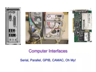
Computer Interfaces Serial, Parallel, GPIB, CAMAC, Oh My!
UCSD: Physics 121; 2012 Common Implementations of Interfaces • Parallel port (8 bits per shot) • Serial (RS-232, RS-485) • usually asynchronous • GPIB (IEEE-488) parallel • General Purpose Interface (or Instrument) Bus • originally HPIB; Hewlett Packard • DAQ card (data acquisition) • like national instruments A/D, D/A, digital I/O • CAMAC • Computer Automated Measurement And Control • VME bus / VXI bus • modern CAMAC-like bus
UCSD: Physics 121; 2012 A quick note on hexadecimal
UCSD: Physics 121; 2012 Hexadecimal, continued • Once it is easy for you to recognize four bits at a time, 8 bits is trivial: • 01100001 is 0x61 • 10011111 is 0x9f • Can be handy because the ASCII code is built around hex: • ‘A’ is 0x41, ‘B’ is 0x42, …, ‘Z’ is 0x5a • ‘a’ is 0x61, ‘b’ is 0x62, …, ‘z’ is 0x7a • ‘^A’ (control-A) is 0x01, ‘^B’ is 0x02, ‘^Z’ is 0x1A • ‘0’ is 0x30, ‘9’ is 0x39
UCSD: Physics 121; 2012 Exchanging Data • Parallel: Fast and expensive • devices A, B simple, but cabling harder • strobe alerts to “data valid” state bit 0 Device A Device B bit 1 bit 2 bit 3 bit 4 bit 5 bit 6 bit 7 strobe • Serial: Slow and cheap • but devices A and must convert between serial/parallel Device A Device B data slide courtesy E. Michelsen
UCSD: Physics 121; 2012 The Parallel Port • Primarily a printer port on the PC • goes by name LPTx: line printer • usually LPT1 • 8 data bits • with strobe to signal valid data • can be fast (1 Mbit/sec) • Other control and status bits for (printer) communication data valid data held static for some interval see http://www.beyondlogic.org/index.html#PARALLEL
UCSD: Physics 121; 2012 Parallel Port Pinout
UCSD: Physics 121; 2012 Parallel Port Access • Most PCs have a DB-25 female connector for the parallel port • Usually at memory address 0x378 • Windows 98 and before were easy to talk to • but after this, a hardware-abstraction layer (HAL) which makes access more difficult • one option is to fool computer into thinking you’re talking to a normal LPT (printer) device • involves tying pins 11 and 12 to ground • Straightforward on Linux • direct access to all pins serial port parallel port
UCSD: Physics 121; 2012 Serial Communications • Most PCs have a DB9 male plug for RS-232 serial asynchronous communications • we’ll get to these definitions later • often COM1 on a PC • In most cases, it is sufficient to use a 2- or 3-wire connection • ground (pin 5) and either or both receive and transmit (pins 2 and 3) • Other controls available, but seldom used • Data transmitted one bit at a time, with protocols establishing how one represents data • Slow-ish (most common is 9600 bits/sec)
UCSD: Physics 121; 2012 Time Is of the Essence • With separate clock and data, the transmitter gives the receiver timing on one signal, and data on another • Requires two signals (clock and data): can be expensive • Data values are arbitrary (no restrictions) • Used by local interfaces: V.35, (synchronous) EIA-232, HSSI, etc. • As distance and/or speed increase, clock/data skew destroys timing sample on rising edge of clock clock sample times centered in data bits data time slide courtesy E. Michelsen
UCSD: Physics 121; 2012 No Clock: Do You Know Where Your Data Is? • Most long-distance, high speed, or cheap signaling is self timed: it has no separate clock; the receiver recovers timing from the signal itself • Receiver knows the nominal data rate, but requires transitions in the signal to locate the bits, and interpolate to the sample points • Two General Methods: • Asynchronous: data sent in short blocks called frames • Synchronous: continuous stream of bits • Receiver tracks the timing continuously, to stay in synch • Tracking requires sufficient transition density throughout the data stream • Used in all DSLs, DS1 (T1), DS3, SONET, all Ethernets, etc. transitions locate data data time interpolated sample times (bit centers) slide courtesy E. Michelsen
UCSD: Physics 121; 2012 Asynchronous: Up Close and Personal • Asynchronous • technical term meaning “whenever I feel like it” • Start bit is always 0. Stop bit is always 1. • The line “idles” between bytes in the “1” state. • This guarantees a 1 to 0 transition at the start of every byte • After the leading edge of the start bit, if you know the data rate, you can find all the bits in the byte transition locates data one byte idle idle 1 0 start bit 0 bit 1 bit 2 bit 3 bit 4 bit 5 bit 6 bit 7 stop time interpolated sample times (bit centers) slide courtesy E. Michelsen
UCSD: Physics 121; 2012 Can We Talk? ASCII “A” = 0x41 9600, 8N1 idle idle • If we agree on 4 asynchronous communication parameters: • Data rate: Speed at which bits are sent, in bits per seconds (bps) • Number of data bits: data bits in each byte; usually 8 • old stuff often used 7 • Parity: An error detecting method: None, Even, Odd, Mark, Space • Stop bits: number of stop bits on each byte; usually 1. • Rarely 2 or (more rarely) 1.5: just a minimum wait time: can be indefinite start bit 0 bit 1 bit 2 bit 3 bit 4 bit 5 bit 6 bit 7 stop 1 bit @ 9600 bps = 1/9600th sec 9600, 7E2 idle idle start bit 0 bit 1 bit 2 bit 3 bit 4 bit 5 bit 6 parity stop 1 stop 2 slide courtesy E. Michelsen
UCSD: Physics 121; 2012 RS-232: most common implementation • RS-232 is an electrical (physical) specification for communication • idle, or “mark” state is logic 1; • 5 to 15 V (usually about 12 V) on transmit • 3 to 25 V on receive • “space” state is logic 0; • +5 to +15 V (usually ~12 V) on transmit • +3 to +25 V on receive • the dead zone is from 3 V to +3 V (indeterminate state) • Usually used in asynchronous mode • so idles at 12; start jumps to +12; stop bit at 12 • since each packet is framed by start/stop bits, you are guaranteed a transition at start • parity (if used) works as follows: • even parity guarantees an even number of ones in the train • odd parity guarantees an odd number of ones in the train
UCSD: Physics 121; 2012 GPIB (IEEE-488) • An 8-bit parallel bus allowing up to 15 devices connected to the same computer port • addressing of each machine (either via menu or dip-switches) determines who’s who • can daisy-chain connectors, each cable 2 m or less in length • Extensive handshaking controls the bus • computer controls who can talk and who can listen • Many test-and-measurement devices equipped with GPIB • common means of controlling an experiment: positioning detectors, measuring or setting voltages/currents, etc. • Can be reasonably fast (1 Mbit/sec)
UCSD: Physics 121; 2012 Data Acquisition • A PCI-card for data acquisition is a very handy thing • The one pictured at right (National Instruments PCI-6031E) has: • 64 analog inputs, 16 bit • 2 DACs, 16 bit analog outputs • 8 digital input/output • 100,000 samples per second • on-board timers, counters • Breakout box/board recommended
UCSD: Physics 121; 2012 CAMAC • This somewhat old interface provides a “crate” into which one slides modules that perform specific tasks • A/D conversion • time-to-digital converters • pulse generators • charge measurement • amplifiers • delay generators • Frequently used in timing experiments, like nuclear physics: catch events in detector, generate signal, measure strength, etc. • Often the modules are highly multiplexed (16 channels per card common)
UCSD: Physics 121; 2012 CAMAC crate (above) and inhabitants (right) including two custom modules, two commercial time-to-digital converters (TDCs) and the crate controller (note interface cable (50-pin SCSI-2 style)
UCSD: Physics 121; 2012 CAMAC features • 16-bit (newer are 24-bit) data words • Full command cycle in 2 s 8 Mbit/sec • Look-At-Me (LAM) interrupts computer when some event happens • Commands follow N.A.F. sequence: slot number, address, function • so address specific modules by name/position • A and F values perform tasks that are defined by module • A often refers to channel number on multiplexed device • F might indicate a read, a write, a reset, or other action
UCSD: Physics 121; 2012 Example Interface: APOLLO • APOLLO is a lunar ranging apparatus that fires 20 laser pulses per second at a selected lunar reflector, measuring the time-of-flight of photons making the round trip • Besides the essential function of data collection and apparatus coordination, we wanted remote operation capability • We also required strict thermal control
UCSD: Physics 121; 2012 Catalog of APOLLO Interfaces • Uses a Linux PC (runs for a year at a time, no crashes) • Two GPIB devices • GPS-disciplined clock; actuated optics (mirror tilt, lens focus) • 5 RS-232 devices • motor that spins optic (8N1 @ 57600); laser control (8E1 @ 9600); CCD camera control (8N1 @ 115200); laser power meter (bolometer) (8N1 @ 9600); GPS clock (7E1 @ 9600) • CAMAC crate with two devices • TDC for 10 ps timing; custom module to control timing • another device sits passively in crate, no access to dataway • DAQ card for analog input, digital output • analog inputs for RTDs (temperature); flow meters; pulse energy; telescope tilt angle • digital outputs for relay control: turning devices on and off • Parallel port used for additional digital outputs for more relays
UCSD: Physics 121; 2012 RTD Readout Scheme
UCSD: Physics 121; 2012 Example Temperature Record
UCSD: Physics 121; 2012 Reading • Read 6.7.3; skim 6.7.5; read 6.7.7; 6.7.9