Download
1 / 19
190 likes | 341 Views
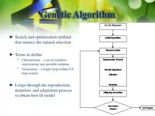
Remote Controller Design of Networked Control System using a Genetic Algorithm. Prepared by: Ronald Fenton ECE 7550 – Distributed Control Systems Focus Independent Study Project. Outline. Introduction Networked Control System Genetic Algorithm Controller Design Conclusion. Introduction.

E N D
Remote Controller Design of Networked Control System using a Genetic Algorithm Prepared by: Ronald Fenton ECE 7550 – Distributed Control Systems Focus Independent Study Project
Outline • Introduction • Networked Control System • Genetic Algorithm Controller Design • Conclusion
Introduction • Networked Control Systems -Why? • As the number of devices in a system grow and the functions of a system need to be more intelligent, the devices need to exchange rapidly increasingly amounts of data. • Conventionally, these devices have been connected and data has been exchanged with point-to-point or direct cable connections. • The main problem with this approach lies in the fact that as the number of devices increases the number of cables increases proportional to the number of devices. • Networked Control –Answer! • In order to solve this problem, various serial communication networks have been designed to provide efficient and reliable communication paths for data exchange among devices. • These networks have become known as fieldbuses which include Profibus, World FIP, Fieldbus Foundation, Controller Area Network (CAN), and LonWorks.
Introduction (cont) • Networks can be divided into two groups: real-time and non-real-time data. • Non-real-time: this network does not have stringent time limits on their delays during data exchange. • In these systems the concern is over whether the data arrives without error and duplication • Real-time: this network has strict time limits and the data’s value is diminished as the system delay grows larger. • In these systems the concern is over the time taken to reach the destination • Periodic – data comes across the network at specified periods of time. • Asynchronous – data comes across the network at different, unspecified times.
Networked Control System (NCS) • PROFIBUS is a fast, open bus system widely used in automation technology. It is internationally standardized and is divided into three versions: • PROFIBUS-FMS (Fieldbus Message Specification), is used primarily for communication between controllers. • PROFIBUS-PA (Process Automation) is based on an intrinsically safe physical layer, and is intended for process automation. • PROFIBUS-DP (Distributed Peripherals) is designed for fast data exchange at the sensor/actuator level.
NCS Structure • The master and slave stations consist of an input/output data process, communication process, and I/O instrumentation process. • The communication is achieved by a communication cycle and instrumentation cycle in the NCS. • In the communication cycle, control information of master and output information of slave are exchanged using DPRAM. • In the instrumentation cycle, information for plant control is exchanged using the I/O instrumentation process. • Master station operational procedure • The I/O data process using DP master service functions begins to operate for exchange of information with the slave. • The input data process reads a feedback signal from its DPRAM input buffer, and forwards to the output data process. • The control algorithm is then implemented in the output data process generates a control signal using the plant feedback signal , and writes to the DPRAM output buffer for transmission to the slave station
NCS Structure (cont) • Slave station operational procedure • The input data process reads a control signal from the DPRAM input buffer, and forwards to the output data process. • The driver software within the output data process drives the plant following the control signal , and writes to the DPRAM output buffer in order to transmit feedback signal of the plant to the master • Because the control and feedback systems are being transmitted over the Profibus-DP network, some amount of network delay is inevitable since several different plants may be sharing the network.
NCS Network Delay • Transmission and Reception Times • Ts is the communication period of the master station (equal to the sampling time of the network). • Tp is the sum of processing time of the I/O process to read from or write on the DPRAM. • TT is the communication process time needed to prepare and send a message while the assumption is made that the time required to receive a message was negligible. • T1 is the processing time of the instrumentation process, and TC is the time required to transmit a message of the network. • Network delay caused by Complete Synchronization • Times delays that are caused by the processing time of each process and the polling mechanism of the Profibus-DP network. • 1. Master station generates a control signal and writes it to the DPRAM. • 2. The communication process begins transmitting the signal after processing. • 3. The slave station receives the the control signal and writes it to DPRAM. • 4. The slave then reads/forwards the control signal to the instrumentation process • 5. Finally, the instrumentation process drives the plant and generates a feedback signal, that is delayed until the next polling by the master station right after the next control signal was sent.
NCS Network Delay (cont) • Network delay caused by Lack of Synchronization • Time delays caused because the communication of control signals and feedback signals are not periodic in nature. • Because the I/O data process and communication process are not synchronized the control signal was not transmitted until the next cycle. • If the I/O data process and instrumentation process are not synchronized, then it will not send the control signal until the next communication process. • Therefore, the network delay increases having to wait for each communication process and the network delay ends up as follows:
Remote Controller by Genetic Algorithm • For the following networked control system, the plant and remote PID controller are connected via the Profibus-DP network. • However; due to the fact that there is an inherent time delay on the network (periodic or asynchronous), the remote PID controller parameters had to adapt. • Therefore, a “Genetic Algorithm” was constructed which would adapt the controller parameters real time. • Fitness Calculator – calculates the fitness values of each PID parameter based on system performance (y(t), overshoot, settling time). • Genetic Algorithm Core – includes genetic operations such as crossover, mutation, and reproduction. • PID Gain Calculator – converts GA strings back into PID gains.
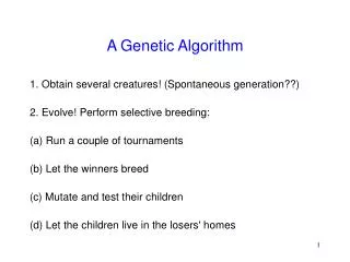
Remote Controller by Genetic Algorithm • 1. Select design specifications of the control system such as reference input r(t), reference percent overshoot Mpr and reference settling time Tsr, and generate initial population of PID gains using initialization routine of the genetic algorithm. • 2. After reference input is applied to the system, obtain the characteristics of step response such as output y(t); percent overshoot Mpyi; and settling time Tsyi for individual sets of Kpi, Kii, and Kdi. • 3. Calculate fitness value in comparison with the design specifications. • 4. Code three PID gains into a single string using multi-parameter coding, and generate offspring by applying genetic operators. • 5. Decode the strings to PID gains, and repeat from step 2 to step 5 until termination condition is met or a preset number of iterations are performed.
Fitness Function • The fitness function’s purpose provides a measure of the suitability of a string, described best by the “survival of the fittest” principle. • Any string which has a higher fitness value has a higher probability of contributing one or more offspring in the next generation. • Fitness functions were defined as a combination of performance criteria and the time integral of the error. where: at y < r at r < y < 2r at y > 2r • Because generated populations are very similar the fitness values are scaled linearly as follows: where:
Coding and Decoding • Genetic Algorithms work with a population of strings, not the PID values themselves. • For simplicity, the widely used binary code approach for creating strings was used • In many applications the values of parameters are coded directly into binary strings with knowledge of upper and lower bounds; however, this creates difficulties in appropriate resolution when the difference among the parameters are large. • To solve this problem, the PID gains are represented by their scaling factors based on initial gains calculated by Ziegler-Nichols, Root Locus, etc. • 1. Express the PID gains as KpT, KiT, and KdT which are the classically designed controller parameters. Select a string length (n) and magnification factor (m) for the scaling factors, so that the scaling factors have a range of 0 to (2n – 1)*10-m • 2. Calculate the scaled PID gains as follows: Kp = αKpT; Ki = βKpT; and Ki = KpT and convert these values into binary strings. • 3. Allow all genetic algorithm operators to perform; and when all evolutions have ended, covert the best string in the population into a decimal number to obtain the final scaling factors. • 4. Calculate the final PID gains by multiplying the final scaling factors to the base PID gains.
Crossover and Mutation • Single Point Crossover: • one crossover point is selected, binary string from the beginning of the chromosome to the crossover point is copied from the first parent, the rest is copied from the other parent. • 11001011+11011111 = 11001111 • Two Point Crossover: • two crossover points are selected, binary string from the beginning of the chromosome to the first crossover point is copied from the first parent, the part from the first to the second crossover point is copied from the other parent and the rest is copied from the first parent again. • 11001011 + 11011111 = 11011111 • Uniform Crossover (Stochastic Remainder): • bits are randomly copied from the first or from the second parent. • 11001011 + 11011101 = 11011111
Crossover and Mutation • Arithmetic Crossover: • some arithmetic operation is performed to make a new offspring (i.e, and, or, etc). • Mutation • Certain bits within the genetic offspring switch (i.e binary inversion) • 11001001 => 10001001 • 11001011 + 11011111 = 11001001
Conclusions • In conclusion, the paper reviewed focused on the structure of a networked control system and the design of a remote controller which adapted via a genetic algorithm. • They showed that the network delays included network sharing among numerous nodes, processing time at each node, and application processes with lack of synchronization. • The genetic algorithm used to tune a remote controller for networked control showed its feasibility for tuning the gains without any knowledge of network delay. • This approach seems to be work extremely well from the results they came up with. A genetic algorithms allowed them to ignore mathematical computations in controller design due to network delay while retaining system performance parameters by simply adapting PID gains based on those system responses (overshoot, settling time, etc).
References • K. C. Lee, and S. Lee, “Remote Controller Design of Networked Control System using Genetic Algorithm,” Industrial Electronics, 2001. Proceedings. ISIE 2001. IEEE International Symposium on , Volume: 3 , 12-16 June 2001. • http://www.beckhoff.com/english/default.htm?fieldbusbox/b310.htm • http://cs.felk.cvut.cz/~xobitko/ga/