Download
1 / 1
10 likes | 101 Views
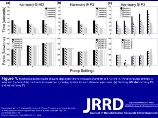
The study compares Harmony HD, P2, and P3 prosthetic vacuum pumps based on time taken to evacuate chambers and maximum force exerted. Methods for characterization of mechanical and electrical prosthetic vacuum pumps. Published in JRRD, 2013.

E N D
Figure 4. Mechanical pump results showing (top plots) time to evacuate chambers to 57.6 kPa (17 inHg) for pump settings (x-axis) and (bottom plots) maximum force exerted by testing system for each chamber evacuated: (a) Harmony HD, (b) Harmony P2, and (c) Harmony P3 Komolafe O, Wood S, Caldwell R, Hansen A, Fatone S. Methods for characterization of mechanical and electrical prosthetic vacuum pumps. J Rehabil Res Dev. 2013;50(8): 1069–78. http://dx.doi.org/10.1682/JRRD.2012.11.0204