Download

1 / 51
520 likes | 673 Views
ENG6530 Reconfigurable Computing Systems. Dynamic Run Time Reconfiguration Operating System Support & Embedded Systems. Function C1. Function B1. Function A1. Partial Bit Files. Dynamic Partial Reconfiguration. Full Bit File. Function C2. Function B2. Function A2. Function A3.

E N D
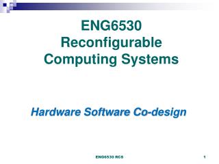
ENG6530 Reconfigurable Computing Systems Dynamic Run Time Reconfiguration Operating System Support & Embedded Systems
Function C1 Function B1 Function A1 PartialBit Files Dynamic Partial Reconfiguration Full Bit File Function C2 Function B2 Function A2 Function A3 Configuration Port Configuration Port or ICAP Partial Reconfiguration is the ability to dynamically modify blocks of logic while the remaining logic continues to operate without interruption. Computation sequences are not know at compile time. The system decides, respectively reacts dynamicallyto application driven reconfiguration requests. ENG6530 RCS
Dynamic Reconfiguration Reconfiguration Overhead Configuration Overhead Function Power On Shut Down Time • A subset of the configuration data changes… • But logic layer continues operating while configuration layer is modified… • Configuration overhead limited to circuit that is changing… • Main problem is the speed of reconfiguration!! ENG6530 RCS
Partial Reconfiguration Technology and Benefits • Partial Reconfiguration enables: • System Flexibility • Perform more functions while maintaining communication links • Size and Cost Reduction • Time-multiplex the hardware to require a smaller FPGA • Power Reduction • Shut down power-hungry taskswhen not needed • Fault Tolerant/self-repairing Systems • Adaptive System ENG6530 RCS
Power Reduction Techniques with PR • Many techniques can be employed to reduce power • Swap out high-power functions for low-power functions when maximum performance is not required • Swap out high-power I/O standards for lower-power I/O when specific characteristics are not needed • Swap out black boxes for inactive regions • Time-multiplexing functions will reduce power by reducing amount of configured logic ENG6530 RCS
Run-time Reconfiguration Applications Applications for non-frequent reconfiguration • Rapid prototyping, • Searching (text, genetic database) • Mode changing (test equipment, radio) • Self-repair / self-optimizing Applications for high-speed reconfiguration (area saving) • Networking (exchange packet filters according to traffic) • Modulation/frequency/encryption hopping in military radios Applications for high-speed reconfiguration (acceleration) • Crypto (e.g. asym. crypto for key exchange & symmetric for data) ENG6530 RCS
FPGA Requirements ENG6530 RCS
FPGA Configuration • Following all CAD steps the end result is a configuration file which contains the information that will be uploaded into the FPGA in order to program it to perform a specific function. • Recall that there are several ports used to configure the FPGA. ENG6530 RCS
SelectMap & ICAP SelectMAP • Four methods of reconfiguring a device, each has applications where desirable • Externally • Serial configuration port • JTAG (Boundary Scan) port • SelectMap port • Internally • Though the Internal configuration access port (ICAP). • ICAP is the Internal Configuration Access Port for Xilinx FPGAs. • It is a functional subset of SelectMapand is accessible internally via a user design • It allows the user design to control device reconfiguration at run-time • To reconfigure the device internally either an embedded microprocessor (micro blaze) or a state machine is needed. ICAP ENG6530 RCS
Reconfiguration Speeds • Table 1 shows a summary of Configuration Speeds for the four options • Table 2 shows example configurations sizes and times for the four options Table 2. Example Configuration Sizes and Times to Configure with JTAG and SelectMAP/ICAP Table 1. Summary of Configuration Options
Configuration Details • Partial bit files are processed just like full bit files • Bit file sizes will vary depending on region size and resource type • Contains address & data, sync & desync words, final CRC value • Partial Reconfiguration time depends on two factors: • Configuration bandwidth • Partial bit file size • Estimate in PlanAhead, confirm in Rawbit file ENG6530 RCS
Bitstream Flow Factors effecting Reconfiguration Time Bitstream length Bitstream transfer Ways to Improve performance: Reduce the bitstream size: Compression Optimize the way the bitstreams are transferred : Improve the ICAP interface Speed. Use Prefetching of the bit-stream ICAP - Flow SystemACE BRAM (Microblaze) ICAP Memory Configuration Memory
Xilinx VirtexFPGA Reconfiguration • An FPGA is reconfigured by writing bits into configuration Memory (CM) • Configuration data is organized into frames that target specific areas of the FPGA through frame addresses • To reconfigure any portion of that frame the partial bitstreams contain configuration data for a whole frame • Reconfiguration times highly depend on the size and organization of the PR regions: • Virtex-II allowed column based PR only • Virtex-4’s allow arbitrarily sized PR regions • Virtex-5/6/7 configure small part of a column at a time
Virtex II Configuration Arch • Virtex II [PRO] Device is column reconfigurable • Each CLB column takes up 1 major frame • Each CLB major frame takes up 22 minor frames • 1 minor frame is the smallest grain of reconfiguration
Reconfigurable Elements • Granularity of reconfigurable regions vary by device family • Virtex-4 examples • Slice region: 16 CLB high by 1 CLB wide • BRAM region: 4 RAMB16 and 4 FIFO16 • DSP region: 8 DSP48 • Virtex-5 examples • Slice region: 20 CLB high by 1 CLB wide • BRAM region: 4 RAMB36 • DSP region: 8 DSP48 • Virtex-6 examples • Slice region: 40 CLB high by 1 CLB wide • BRAM region: 8 RAMB36 • DSP region: 16 DSP48 • Bit file sizes for each of these resource types will vary ENG6530 RCS
FLOW ENG6530 RCS
PR software Support • Initially there was very little software support to assist in generating PR designs and bitstreams • Recently • Xilinx’s EA PR flow with the integration of the Xilinx’s PlanAhead tool greatly mitigates the complicacies of PR
How Can We Reconfigure? • Initiation of reconfiguration is determined by the designer • On-chip state machine, processor or other logic • Off-chip microprocessor or other controller • Delivery of the partial bit file uses standard interfaces • FPGA can be partially reconfigured through the SelectMap, Serial or JTAG configuration ports, or the Internal Configuration Access Port • Logic decoupling should be synchronized with the initiation and completion of partial reconfiguration • Enable registers • Issue local reset ENG6530 RCS
Terminology • Reconfigurable Partition (RP) • Design hierarchy instance marked by the user for reconfiguration • Reconfigurable Module (RM) • Portion of the logical design that occupies the Reconfigurable Partition • Each RP may have multiple Reconfigurable Modules • Static Logic • All logic in the design that is not reconfigurable • Partition Pins • Ports on a Partition; Interface between Static and Reconfigurable Logic ENG6530 RCS
A1 A2 A3 B1 B2 C1 C2 C3 C4 Terminology: Configurations Reconfigurable Modules RP “A” RP “B” RP “C” Static • A Configuration is a complete FPGA design • Consists of Static Logic and one variant for each reconfigurable instance • Maximum number of RMs for any RP determines minimum number of Configurations required • Example: Possible Configurations for this design • Static + A1 + B1 + C1 • Static + A2 + B2 + C2 • Static + A3 + B2 + C3 • Static + A3 + B2 + C4 ENG6530 RCS
Terminology: Bus Macros • Bus Macros: Means of communication between PRMs and static design • All connections between PRMs and static design must pass through a bus macro with the exception of a clock signal • Type of Bus Macros • Tri-state buffer (TBUF) based bus macros • Slice-based (or LUT-based) bus macros ENG6530 RCS
Design Flow • The partial reconfiguration implementation process is broken down into three main phases: • Initial Budgeting Phase – Creating the floorplan and constraints for the overall design • Active Module Phase – Implementing each module through the place and route process. • Final Assembly Phase – Assembling individual modules together into a complete design. ENG6530 RCS
Module A ICAP Module C Controller (Microblaze) Flash controller Module B Modules: A and B PRR 1 Static modules PRR 2 Modules: C Current PR Design Flow • Steps • Partition the system into modules • Define static modules and reconfigurable modules • Decide the number of PR regions (PRRs) • Decide PRR sizes, shapes and locations • Map modules to PRRs • Define PRR interfaces, instantiate slice macros for PRR interfaces • Optimization problems • Design partitioning • Number of PRRs • PRR sizes, shapes and locations • Mapping PRMs to PRRs • Type and placement of PRR interfaces Design partitioning Design floorplanning and budgeting Static modules Reconfigurable Modules (PRMs) FPGA Static region 2 # of PRRs 1 ENG6530 RCS
Conclusions • Local Run Time Reconfiguration (LRTR) provides flexibility and more efficient usage of the FPGA fabric. • Continuous service applications • Reduced power consumption • Reduced device count • In the field hardware upgrades … • Local Run-Time Reconfiguration requires • Tools that could automate the process • Supports such as Operating Systems and on-chip soft/hard cores to manage the complexity. • In order to exploit fully RTR one would need access to devices that could be reconfigured hundreds of thousands of times per second. ENG6530 RCS
OS Support for RCS ENG6530 RCS
Reconfigurable Operating Systems • Modern FPGA can be partially dynamically reconfigured. This feature adds tremendous flexibility to the Reconfigurable Computing (RC) Field but also introduces challenges. • Reconfigurable Operating Systems tend to: • Ease applications development, • Higher lever of abstraction • Ease application verification and maintenance. ENG6530 RCS
OS for RCS • With the development of the reconfigurable computing systems, designers are looking towards multitasking reconfigurable computers • Multitasking an FPGA will require an OS to manage the loading, swapping and allocation of the tasks to the FPGA surface • As the status of the FPGA changes in time, the designs will have to be completed at run-time, and not statically compiled. • The partitioning, placement and routing need be handled by the OS. ENG6530 RCS
Module A ICAP Module C disabled Module A Module A Controller (Microblaze) Flash controller Module B disabled Module B Module B Module C Module C A System Controller Battery FPGA disabled enabled JTAG Base system configuration Bitstreams storage enabled External I/O Reconfigurable area Module A request Static area 1. System controller does not need to be placed in an external device 2. Access to fast Internal Configuration Access Port (ICAP – 32 bits, 100 MHz) 3. Smaller partial bitstreams 4. No need to halt complete system when reconfiguring a module 5. Time multiplexing of FPGA resources, load and unload HW modules on demand
Tasks of OS for RCS • General Tasks • Loader • Scheduler • Memory management • Circuit protection • I/O • Inter-process communication • Special Tasks • Allocation • Partitioning • Placement • Routing multiple circuits on one or more FPGA ENG6530 RCS
The Design Stages • Allocation • Deciding which part of the FPGA is available and can accommodate the incoming task New application requiring six contiguous spaces ENG6530 RCS FPGA Surface
Allocation Algorithm • Determines the total area required for the application and calculates the optimal circuit dimensions (the OS limits it to rectangles). • Determines if there is available FPGA logic. • If the circuit is unable to be allocated in its current shape it calculates the largest FPGA logic area available. ENG6530 RCS
Dynamic Partitioning • Breaking a task graph down into smaller components so they are able to fit onto an available space on the FPGA surface Circuit Design ENG6530 RCS
Placement • What nodes of the application get mapped to what FPGA cells? 2 3 4 1 5 6 3 6 5 1 4 2 ENG6530 RCS Allocated, Partitioned Circuit FPGA partition
Fast Configuration • Reconfiguration time is non- productive time • Reconfigure the device as fast as possible in order to minimize reconfiguration overhead Techniques for fast reconfiguration • Configuration prefetching • Configuration compression • Relocation and Defragmentation • Configuration caching ENG6530 RCS
Configuration Prefetching • Loading a configuration onto a device in advance, in order to overlap reconfiguration with useful computation Configuration Prefetching issues • Can be exploited if configuration can be done concurrently with computations • Requires prediction which configuration will be needed in next couple of milliseconds • Gets complicated when multiple branches exist in program ENG6530 RCS
Configuration Compression Minimize the amount of data that must be loaded to the device in multi-context environment • Additional decompression circuits must be put on the FPGA die Configuration Caching Reducing the amount of configuration data that must be transferred to the device • Use fast cache near reconfigurable hardware ENG6530 RCS
New configuration c5 c5 c1 c3 c1 Relocation / defragmentation c2 c3 c2 c4 c4 Relocation and Defragmentation • Loading and uploading configurations fragments free space • May reconfigure any part of the device • Configurations most likely occupy contiguous areas • Relocation needed if fragmentation of a free space prevents loading new configurations ENG6530 RCS
UG-PDROS ENG6530 RCS
Reconfigurable OS Essential Components PRRs + GPs Scheduler Placer Bitstream Manager Communication network ENG6530 RCS
Overall System Components ENG6530 RCS
Task Representation • A DFG is a directed graph that represents dependencies (arrows) between tasks (nodes). Where each task represented by a node. • Task Type can be: • HW • SW • HybridHW • HybridSW ENG6530 RCS
DFG Generator • A DFG Generator is needed in order to evaluate the proposed schedulers and framework. • It randomly generates DFGs with predefined specification, such as • Number of nodes, • Task types and • Total number of dependencies per DFG ENG6530 RCS
DFG Generator outputs {.id= 0 , .operation= OPMult, .mode =HybHW , .next= 1 ,.initPrio=0, .TypeID=3,.CanRun=0x1F, .D={.op1= 2 ,.op2= 1, .isAdd_op1= NO, .isAdd_op2= NO }, .Emu={.HWdelay=TASK_3_HW_DELAY, .SWdelay=TASK_3_SW_DELAY} }, ENG6530 RCS
Scheduling Algorithms • Scheduling algorithms have great impact on performance. • The total time it takes to run the same tasks set on the same platform could be minimized using different schedulers. • Many other factors can be used to evaluate schedulers performance such as : • Power consumption, • Reconfiguration time ENG6530 RCS
Scheduling Algorithms In this work we propose several novel scheduling algorithms for reconfigurable computing that canhandle both hardware and software tasks. The algorithms proposed tends to reusehardware tasks to reduce reconfiguration overhead, Migrate tasks between software/hardware to efficiently utilize resources and, Reduce computation time ENG6530 RCS
Results • Schedulers validation needs extensive testing using benchmarks with different parameters, properties, and statistics. • Several DFGs were used, these DFGs differ by the number of • Tasks, • Dependencies, and • Operations. • Each scheduler was tested with different number of PRRs for every DFG. • To get more reliable results, each DFG is run six times using the same configuration • The results were repeated with uniform and no-uniform PRRs. ENG6530 RCS
Results Total Time for the Uniform implementation
Module A ICAP Module C Controller (Microblaze) Flash controller Module B Modules: A and B PRR 1 Static modules PRR 2 Modules: C OS Resource Management • Optimization problems • Design partitioning • Number of PRRs • PRR sizes, shapes and locations • Mapping PRMs to PRRs • Type and placement of PRR interfaces • These paramaters affect the performance of the applications being executed on the FPGA platform. • Can we estimate or predict these resources?? Static modules Reconfigurable Modules (PRMs) FPGA Static region 2 # of PRRs 1 ENG6530 RCS
Adaptive Resource Allocation • A Task Graph Generator is used to create hundreds of DFGs. • A set of features is then extracted from each DFG. • Each DFG is simulated using different problem parameters. • The resulting data is then cleaned. • The WEKA data-mining package is used for classification (i.e., prediction). • Several Learning Techniques are utilized, including ANNs, SVM, and KNN. • Ten-fold cross validation is used to validate the model • The System is currently used to predict the layout and necessary resources. ENG6530 RCS
Conclusions • Run Time Reconfiguration (RTR) provides flexibility and more efficient usage of the FPGA fabric. • RTR allows the exploitation of dynamic conditions or temporal locality within application-specific problems • Run-Time Reconfiguration requires • Tools that could automate the process • Supports such as Operating Systems and on-chip soft/hard cores to manage the complexity. • Combining Meta-heuristic based techniques along with Machine learning could help in creating smart Operating Systems that can enable dynamic run time reconfiguration in embedded systems. ENG6530 RCS