PBC Method Flat Mirror
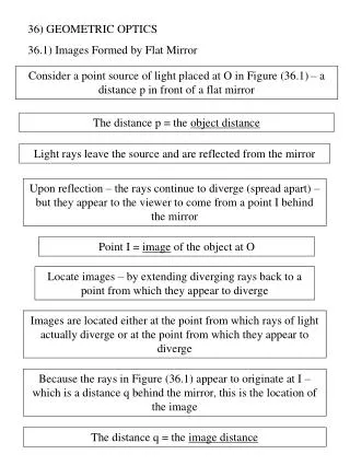
Gas Mixture. Dielectric Mirror. PBC Method Flat Mirror. Pump. Window. PM. PBC. HR Coated Fiber Tip. SMF. PBGF. Light. PM. Vacuum. Collimating Lens. Dielectric Mirror. PBC Method Curved Mirror. Pump. PM. PBC. HR Coated Fiber Tip. SMF. PBGF. Light. PM. Vacuum.


PBC Method Flat Mirror
E N D
Presentation Transcript
Gas Mixture Dielectric Mirror PBC Method Flat Mirror Pump Window PM PBC HR Coated Fiber Tip SMF PBGF Light PM Vacuum Collimating Lens
Dielectric Mirror PBC Method Curved Mirror Pump PM PBC HR Coated Fiber Tip SMF PBGF Light PM Vacuum
Conflat flange for windows O-ring groove to be machined on opposite of knife edge Quantity: 4 O-ring : ID = 0.737” Thickness = 0.103” ¼” Deep Tapped hole for 4- 40 screw 2.75” Conflat flange with 0.505” Bore hole (already purchased this way) • Enlarge bore hole to diameter = 0.637” • (radius = 0.3185”) • Groove width = 0.103”x30% = 0.1339” • Groove depth should be 70% of 0.103” = .0721” • Bottom of groove should be smooth for “O” ring vacuum seal Radius = 0.6125” Holes are 120° apart Lesker flange part #s: 0.505” Bore - F0275X050N Blank – F0275X000N 0.637” OD = ID + 2x(thickness + 30%) = 0.737” + 2x(0.103”+.0309”) = 1.0048” 0.737” Will have 1” wedge window to install with teflon holder so that when chamber is brought to atmosphere, window doesn’t fall off (next page) 1.0048” 2.75” Tapped holes are on both sides offset by 60 degrees to not interfere with each other. SIDE:
Teflon window holder Quantity: 4 Should be large enough to fit 4-40 screw (#30 drill size = 0.1285” for free fit) Counter bore for screw head Raw teflon tube OD=1.55” ID=0.75” Top Side 0.6125” Holes are 120 deg apart Radius = 0.6125” 0.25” 1.05” 0.75” 1.05” • Recess to “catch” window • 0.05” bigger than window • Depth of recess needs to be 0.050” 1.55”
Quantity: 4 Fiber holder Swagelok: SS-1-UT-A-4 (1/16” tubing hole) Ultra-Torr Vac fitting “adapter” Collar to attach to vacuum chamber (threads welded to flange): A&N corporation S-50-KM (0.515” ID, 5/8” tube OD) 1/16 ” tube hole 3/16 ” 1/4 ” ½” OD tubing Overall length needs to be ~6”, so ½” OD tubing should probably be about 5” Mike wasn’t sure what this piece was, though it is important for the interior to be conical so that the fiber will be guided through.
Conflat flange for fiber holder Quantity: 3 O-ring : ID = 0.737” Thickness = 0.103” 2.75” Conflat flange • Bore hole to diameter = 0.620” • (radius = 0.310”) Lesker flange part #s: 0.505” Bore – F0275X050N Blank – F0275X000N 0.620” 2.75” SIDE:
Chamber Layout C2H2 Buffer Gas