Download
1 / 22
220 likes | 309 Views
Information-Theoretic Study of Optical Multiple Access. Jun Shi and Richard D. Wesel UCLA 01/14/05. Princeton’s Scheme. Princeton uses a (4,101) 2D prime code. wavelength. 2 3 4 5 6 7 8 9 10 11 99 100 101 Time. User 1 User 2 User 3.

E N D
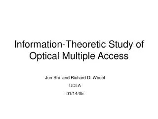
Information-Theoretic Study of Optical Multiple Access Jun Shi and Richard D. Wesel UCLA 01/14/05
Princeton’s Scheme • Princeton uses a (4,101) 2D prime code. wavelength • 2 3 4 5 6 7 8 9 10 11 99 100 101 • Time User 1 User 2 User 3
The (4,101) code • Asynchronous, coordinated. • Each bit takes 4 time/wavelength slots. • 1’s density per user (chip level) =4/808≈0.005 • 1’s density per user (bit level) =1/2. • Upper bound on BER:
The Z-channel • All other users are treated as noise. • Each user sees a Z-channel • Throughput (Sum-rate) : 1 1 Pe 0 0
User 1 User 2 Double-Interference • Due to asynchronism, in the worst case, a one from an interferer affects two bits of the desired users. • Asynchronous channel is very complicated. The exactly capacity is still under investigation, but here is an approximation: synchronous double-interference User 1 p receiver 2p 2p 2p User 2 User 3 User 4
The Ideal case • Under perfect synchronism and with joint decoding (other users are not noise but information), the throughput is a constant equal to 1bit/transmission. • Let input 1’s density be 0.005, the chip density of Princeton’s scheme, we can plot throughput vs. # of users.
Random Codes • In Princeton’s approach, prime codes are assigned a priori, which requires coordination. • We can assign the patterns randomly.
Prime code constraint • Princeton’s scheme is slightly better at small number of users while random code shows advantages with large number of users. • This is due to the requirement that a prime codeword has at most one slot per wavelength, increasing the probability of collision.
Error Correcting Codes • Prime codes do not correct errors. To achieve capacity, error-correcting codes are required. • Encoding and decoding can be done in FPGA boards. This is an item for future work in Phase II. Decoder LDPC Encoder Data 1 User 1 Decoder Data 2 LDPC Encoder User 2
Successive Decoding • We can decode the first user by treating others as noise, then the first user’s ones become erasures for the other users. Proceed in this way until finish decoding all the users. • This is called successive decoding. For binary OR channel, this process does not lose capacity as compared to joint decoding.
A 3-user example R1 1 User 1 User 2 User 3 1 1 R3 R2 User 1 1 1 User 2 User 3 0 0 Receiver
A 3-user example R1 1 User 1 User 2 User 3 1 1 R3 R2 User 1 1 1 User 2 e User 3 0 0 Receiver
A 3-user example R1 1 User 1 User 2 User 3 1 1 R3 R2 User 1 1 1 User 2 e User 3 0 0 Receiver
A 3-user example R1 1 User 1 User 2 User 3 1 1 R3 R2 User 1 User 2 User 3 Receiver
Density Transformer • To achieve capacity and apply successive decoding, a key thing is to get the right one’s density. This is an item for future work under Phase II. LDPC Encoder ½ Density Transformer ½ Source 1 p1 ½ p2 LDPC Encoder Density Transformer ½ Source 2 p3 ½ LDPC Encoder ½ Density Transformer Source 3
Synchronization • In successive decoding, the receiver only needs to be synchronized to one user at a time.
Multiple looks • To further increase the throughput, we should not treat other users as interference but as useful information. • We want the receiver to align with each of the users, not just one user. • This can be done in a star network where the receiver has all the information.
A 2-user example x11, x12, x13, … 2 looks User 1’s clock y11, y12, y13, … Receiver x21, x22, x23, … y21, y22, y23, … User 2’s clock Receiver’s clocks
Joint Decoding LDPC Encoder Data 1 User 1 Joint Decoder Data 2 LDPC Encoder User 2