Background knowledge Magnetic field
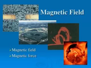
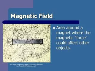
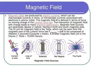
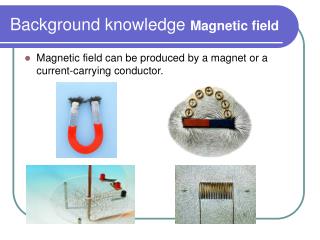
Background knowledge Magnetic field. Magnetic field can be produced by a magnet or a current-carrying conductor. Neutral point. N S. x. N N. Magnetic field lines. Magnetic field lines are used to show the strength and direction of a magnetic field. Note:

Background knowledge Magnetic field
E N D
Presentation Transcript
Background knowledge Magnetic field • Magnetic field can be produced by a magnet or a current-carrying conductor.
Neutral point • N S x N N Magnetic field lines • Magnetic field lines are used to show the strength and direction of a magnetic field. Note: 1. Field lines run from the N-pole round to the S-pole. 2. When field lines are closely-spaced, field is strong and vice-versa.
S N Example 1 (a) • In each of the following cases, draw the magnetic field lines between the magnets and mark the positions of the neutral points (if any).
N S Example 1 (b) • In each of the following cases, draw the magnetic field lines between the magnets and mark the positions of the neutral points (if any).
S S Example 1 (c) • In each of the following cases, draw the magnetic field lines between the magnets and mark the positions of the neutral points (if any).
Example 1 (d) • In each of the following cases, draw the magnetic field lines between the magnets and mark the positions of the neutral points (if any).
Earth’s magnetic field • The Earth has a weak magnetic field. It is so weak that it does not affect much the field patterns of permanent magnet. • It is rather like the field around a huge bar magnet. • The south pole of the ‘earth magnet’ is actually in the north.
BV B N a BH ground Earth’s magnetic field • It is convenient to resolve the earth’s field strength B into horizontal and vertical component, BH and BV respectively. We have BH = Bcos a and BV = Bsin a. Compass needles, whose motion is confined to a horizontal plane, are affected by BH only.
F Magnetic force current B I Fleming’s left-hand rule • F: force • B: magnetic field • I: current
F Magnetic force current B I Factors affecting magnetic force • B: magnetic field • I: current • l: length of conductor in B-field
Current balance • magnetic force F acting upwards • weight of the rider is equal to the magnetic force when the frame PQRS is balanced.
magnetic force and current • Record the currents required to balance different number of identical riders on PQ. • Results: magnetic force (number of riders) current • i.e. F I
magnetic force and length • Keep the current through PQ constant. • Record the number of riders required to balance the metal frame when one, two and three pairs of equally strong magnadur magnets are used as shown. • Results: The magnetic force (number of riders) length of conductor (number of pairs of magnadur magnets) i.e. F l
magnetic force and magnetic field • Replace the magnadur magnets by a coil of many turns (for example 1100 turns) as shown below. • Hence, the magnetic field is provided from the coil and the magnetic field can be increased by increasing the coil current. • Keep the current through PQ constant. • Record the coil currents required to balance different number of identical riders on PQ. • Results: The magnetic force (number of riders) magnetic field (coil current) i.e. F B
Conclusion • The magnetic force is increased if • the current is increased, (F I) • the magnetic field is increased, (F B) • there is a greater length of wire inside the magnetic field. (F l)
Precautions of using current balance • Make sure the direction of the magnetic field is perpendicular to the current-carrying arm. • Minimize the effect of the earth’s magnetic field by aligning the current-carrying arm along the N-S direction. • The set-up should be far from any current-carrying conductors so as to avoid the effect of stray magnetic fields. • To avoid overheating, the current should be switched off as soon as measurements have been taken. • Shield the set-up from the disturbance of wind.
Magnetic flux density B • Definition: • Electric field E: force per unit charge (E = F / Q) • Gravitational field g: force per unit mass. (g = F / m) • Magnetic flux density B (magnetic field): force acting per unit current length. (B = F / Il ) • In words: The magnetic flux density B is equal to the force acting on a conductor of unit length and carrying a unit current at right angles to the field. • Unit of B: Tesla (T) or N A-1 m-1
I sin q I l B I cos q q Magnetic force on a current-carrying conductor • From definition: B = F/Il • F = BIl • If the conductor and field are not at right angles, but make an angle q with one another, the expression becomes F = BIl sin q. • Note that: 1. when q = 90o (conductor ⊥ field), F = BIl. 2. when q = 0o (conductor // field), F = 0.
conductor containing n particles each having charge q Magnetic force on moving charge in a magnetic field • Current = Q / t
conductor containing n particles each having charge q Magnetic force on moving charge in a magnetic field • Magnetic force acting on each moving charge • If the conductor makes an angle q with the magnetic field, • F = Bqv sinq
Magnetic field B +q v Motion of a charged particle in a magnetic field • 1 Moving parallel to the field • When a charged particle moves parallel to the magnetic field, i.e. q = 0o, there is no force acting on it. Its velocity remains unchanged and its path is a straight line.
Circular path of motion of +q uniform magnetic field B uniform magnetic field B +q +q 2 Moving perpendicular to the field • Radius of circular path
Circular path of motion of +q uniform magnetic field B uniform magnetic field B +q +q 2 Moving perpendicular to the field • Period of circular motion
Circular path of motion of +q uniform magnetic field B uniform magnetic field B +q +q 2 Moving perpendicular to the field • Notes: • The magnetic force is always perpendicular to the motion of the charged particle; no work is done by the magnetic field. • Kinetic energy of the charged particle remains constant.
Example 2 • The path of an electron in a uniform magnetic field of flux density 0.01 T in a vacuum is a circle of radius 0.05 m. Given that the charge and mass of an electron are -1.6 x 10⁻¹⁹ C and 9.1 x 10⁻³¹ kg respectively. Find (a) the speed and (b) the period of its orbit. • Solution:
d1 d2 rider Magnetic force BIl mechanical force mg Current balance • To measure steady magnetic field by using principle of moment. • Clockwise moment = anti-clockwise moment • mgd2 = BIld1
Example 3 Current balanceA rider of mass 0.084 g is required to balance the frame when an arm PQ, of length 25 cm and carrying a current of 1.2 A, is inside and in series with a flat, wide solenoid as shown below.Find the magnetic flux density inside the solenoid.
Search coil and CRO • A search coil is only used in measuring a varying magnetic field. • A typical search coil consists of 5000 turns of wire and an external diameter d ≤ 1.5 cm so that it samples the field over a small area. • The search coil is placed with its plane perpendicular to a varying magnetic field.
Search coil and CRO • Due to the change of magnetic flux, an e.m.f., which is induced in the search coil, can be measured by a CRO. • The induced e.m.f. E is proportional to the flux density B and the frequency f of the varying magnetic field. i.e. E Bf • The earth’s magnetic field can be ignored because it is a steady field.
Cathode-ray oscilloscope (CRO) • The CRO is a perfect voltmeter as its resistance is very high. It can measure both d.c. and a.c. voltages and show how they vary with time. simulation
Measuring d.c. voltages • To measure a d.c. voltage, the time base is usually switched off. Thus, it is the light spot which is deflected. • Or the time base may be switched on to any high value so that the horizontal trace is deflected. From the deflection on the screen and the gain control setting, the d.c. voltage is then calculated. Y-gain control: 2 V cm-1 • Vd.c. = amount of deflection (cm) x Y-gain control setting (V cm-1) • = 3 x 2 = 6 V
Measuring a.c. voltages • To measure an a.c. voltage, the time base is usually switched off. The waveform displayed becomes a vertical trace so that the amplitude can be easily read on the screen. The maximum voltage or peak voltage is then calculated from the gain control setting. Note that the peak voltage refers to half the length of the vertical trace. Y-gain control: 5 V cm-1 Time base setting: 10 ms cm-1 Peak voltage = Period = Frequency =
1 cm 1 cm Example 4 CRO waveformThe figure below shows a waveform on a screen.(a) If the controls on the CRO are set at 0.5 V cm-1 and 2 ms cm-1, (i) the peak voltage, and (ii) the frequency of the input signal.Solution:
1 cm 1 cm Example 4 CRO waveformThe figure below shows a waveform on a screen.(b) If the gain control is changed to 1 V cm-1, sketch the trace on the figure.Solution:
1 cm 1 cm Example 4 CRO waveformThe figure below shows a waveform on a screen. (c) If the time base control is changed to 5 ms cm-1, sketch the trace on the figure.Solution:
Time base • When Vx increases linearly with time from A to B, the spot of light on the screen moves at a constant speed from the left to right of the screen. • Then the spot of light flies back to the left quickly when Vx suddenly drops from B to C. • The saw-tooth voltage Vx causes no vertical movement of the spot of light..
phase difference f Measuring of phase relationships • The phase difference f of two p.ds (Vx and Vy) can be observed on phase difference f a double-beam CRO.
If a double-beam CRO is not available, the phase difference can be found by applying the two p.ds of the same frequency and amplitude to the X- and Y-plates (time base off) simultaneously. • The phase difference can be determined from the trace on the screen of the CRO as follows. • In general, the trace is an ellipse except when the f is 0o, 90o, 180o, 270o or 360o.
Comparing of frequencies • When two p.ds of different frequencies fx and fy are applied to the X- and Y-plates (time base off), more complex figures are obtained, know as Lissajous’ figures. simulation
Magnetic field around a long straight wire 1. The field lines are circles around the wire. 2. The magnetic field is the strongest close to the wire. 3. Increasing the current makes the magnetic field stronger. 4. Reversing the current also reverses the direction of field lines, but the field pattern remains unchanged.
Right hand grip rule If the right hand grips the wire so that the thumb points the same way as the current, the fingers curls the same way as the field lines.
B ∝ I and B ∝ 1 / r • B ∝ I/r • B = m0I/(2pr) where I is the current and is the permeability of free space (m0 =4px 10-7 T m A-1)
Q P 5 mm 5 mm 5 mm I = 20 A I = 20 A X Y B = m0I/(2pr)(m0 =4px 10-7 T m A-1) • Example 7 • Two long wires X and Y each carries a current of 20 A in the directions as shown in the figure. If the distance between the wires is 10 mm, find the magnitude and direction of the magnetic flux density at • (a) P
Q P 5 mm 5 mm 5 mm I = 20 A I = 20 A X Y B = m0I/(2pr)(m0 =4px 10-7 T m A-1) • Example 7 • Two long wires X and Y each carries a current of 20 A in the directions as shown in the figure. If the distance between the wires is 10 mm, find the magnitude and direction of the magnetic flux density at • (b) Q.