Download
1 / 7
70 likes | 193 Views
Assembly and installation of CLIC TM0 Lab. F. Rossi. July 25, 2012. TM0: accelerating structures. Fiducialisation ( W30) Transport to Lab ( W30) Measurements on girders ( W31) Assembly test for EBW tooling ( W34) Transport to CERN workshop ( W35) EBW of 2 stacks ( W36)

E N D
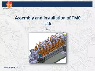
Assembly and installation of CLIC TM0 Lab F. Rossi July 25, 2012
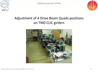
TM0: accelerating structures Fiducialisation (W30) Transport to Lab (W30) Measurements on girders (W31) Assembly test for EBW tooling (W34) Transport to CERN workshop (W35) EBW of 2 stacks (W36) TIG welding of vacuum flanges (W37) Transport to Lab (W38) Installation on girders (W38)
LAB CONFIGURATION: electric networks • Improvement of current electric network of Lab completed • Supporting system for: • Control valves (q.ty 7) • Flow transducer (q.ty 1) • Pressure sensor (q.ty 1) • Electric scheme for control valves, heaters, temperature sensors, etc. under design (J. Blanc) SSR POWER SOCKET Max. 63 A POWER SOCKET Max. 63 A DBQ heaters PETS heater AS heater Temperature sensors (q.ty 29) POWER SOCKET Max. 32 A POWER SOCKET Max. 16 A • CUPBOARD for: • NI cDAQ-9178 8 slots (q.ty 1) • NI cDAQ-9174 4 slots (q.ty 1) • 24 V supply • Digital control electronics for proportional valves (q.ty 7)
LAB CONFIGURATION: hydraulic system Shoaib Azhar
LAB CONFIGURATION: air temperature 1.2 m 1 m 1.3 m 2 m • 5 thermocouples for each section • 15 thermocouples in total • Continuous acquisition during tests NI 9213 16-Channel Thermocouple Input Module