Download
1 / 1
10 likes | 171 Views
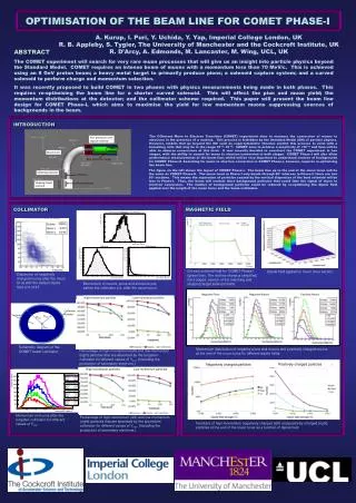
Pions. Negatively charged particles. High-momentum particles. Low-momentum particles. Negative Pions. Negative Muons. Positive Muons. High-momentum particles. Low-momentum particles. Ymin = -125. Pion production and capture solenoid. OPTIMISATION OF THE BEAM LINE FOR COMET PHASE-I.

E N D
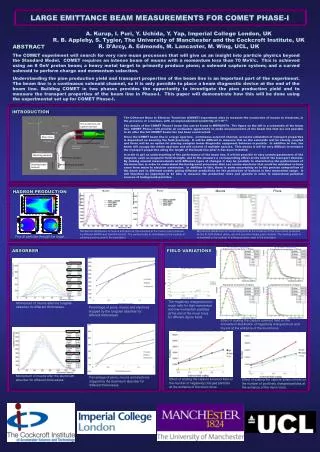
Pions Negatively charged particles High-momentum particles Low-momentum particles Negative Pions Negative Muons Positive Muons High-momentum particles Low-momentum particles Ymin = -125 Pion production and capture solenoid OPTIMISATION OF THE BEAM LINE FOR COMET PHASE-I Positively charged particles Ymin = -100 Muon torus A. Kurup, I. Puri, Y. Uchida, Y. Yap, Imperial College London, UK R. B. Appleby, S. Tygier, The University of Manchester and the Cockcroft Institute, UK R. D’Arcy, A. Edmonds, M. Lancaster, M. Wing, UCL, UK Pion production target Ymin = -75 Muons Electrons ABSTRACT The COMET experiment will search for very rare muon processes that will give us an insight into particle physics beyond the Standard Model. COMET requires an intense beam of muons with a momentum less than 70 MeV/c. This is achieved using an 8 GeV proton beam; a heavy metal target to primarily produce pions; a solenoid capture system; and a curved solenoid to perform charge and momentum selection. It was recently proposed to build COMET in two phases with physics measurements being made in both phases. This requires re-optimising the beam line for a shorter curved solenoid. This will affect the pion and muon yield; the momentum distributions at the detector; and the collimator scheme required. This paper will present the beam line design for COMET Phase-I, which aims to maximise the yield for low momentum muons suppressing sources of backgrounds in the beam. Matching solenoid Collimator Ymin = -50 Stopping target solenoid Stopping target INTRODUCTION The COherent Muon to Electron Transition (COMET) experiment aims to measure the conversion of muons to electrons in the presence of a nucleus. This process is forbidden by the Standard Model (SM) of particle physics. However, models that go beyond the SM such as supersymmetric theories predict this process to exist with a branching ratio that may be in the range 10-13–10-15. COMET aims to achieve a sensitivity of <10-16and thus will be able to observe conversions at this level. It was recently decided to construct the COMET experiment in two stages, with the ability to search for muon to electron conversion in both stages. COMET Phase-I will also allow performance measurements of the beam line, which will be very important to understand sources of backgrounds for COMET Phase-II. Searching for muon to electron conversion in COMET Phase-I, however, requires re-optimising the beam line. The figure on the left shows the layout of COMET Phase-I. The beam line up to the end of the muon torus will be the same as COMET Phase-II. The muon torus in Phase-I only bends through 90owhereas in Phase-II there are two 90osections. This means the separation of particles caused by the vertical dispersion of the bent solenoid will be less in Phase-I. Thus, the beam will contain more background particles that could fake the signal of muon to electron conversion. The number of background particles could be reduced by re-optimising the dipole field applied over the length of the muon torus and the beam collimator. COLLIMATOR MAGNETIC FIELD On-axis solenoid field for COMET Phase-I (green line). The red line shows a simplified, hard-edged, version of the matching and stopping target solenoid fields. Dipole field applied to muon torus section. Dispersion of negatively charged muons after the muon torus with the default dipole field of 0.018T. Momentum of muons, pions and electrons just before the collimator (i.e. after the muon torus). Collimator material Vacuum Rmin Rmax Ymin Schematic diagram of the COMET beam collimator. Momentum distribution of negative pions and muons and positively charged muons at the end of the muon torus for different dipole fields. Percentage of high-momentum (left) and low-momentum (right) particles that are absorbed by the tungsten collimator for different values of Ymin. (Including the production of secondary electrons.) Momentum of muons after the tungsten collimator for different values of Ymin. Percentage of high-momentum (left) and low-momentum (right) particles that are absorbed by the aluminium collimator for different values of Ymin. (Including the production of secondary electrons.) Numbers of high-momentum negatively charged (left) and positively charged (right) particles at the end of the muon torus as a function of dipole field.