Download
1 / 21
210 likes | 364 Views
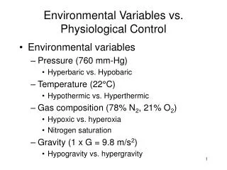
Physiological Control of a Computer Mouse. Presented by Danielle Smith, Shawn Purnell, & Chris Hawk. Outline of Presentation. Project Introduction Background/Theory Block Diagram Hardware Circuit Implementation Software Implementation Results/Discussion Future Developments Conclusion.

E N D
Physiological Control of a Computer Mouse Presented by Danielle Smith, Shawn Purnell, & Chris Hawk
Outline of Presentation • Project Introduction • Background/Theory • Block Diagram • Hardware Circuit Implementation • Software Implementation • Results/Discussion • Future Developments • Conclusion
Introduction • Project Purpose • Acts as a proof of concept project • Simulate low resolution physiological directional control of an automated computer cursor • for paraplegic empowerment • for military strategic targeting systems
Background on Electrodes • Silver/Silver-Chloride Electrodes • Contact/ Capacitive electrodes • Serve as a transducers to change an ionic current into an electronic current • Ag/AgCl Electrodes used for measurements • Electrodes used for EOG • Small with solid gel • Prevent motion artifact and contact with eye • Electrodes used for EMG • Large with liquid gel
EMG and EOG Signals • EMG measurements - lie within muscle movement • Skeletal muscle organized on basis of motor unit • Motor unit - smallest unit that can be activated by volitional effort • Fibers of a given motor unit are interspersed with fibers of other motor units • At high levels of effort and contraction, many motor unit responses are superimposed • Gives Rise to the complicated interference pattern taken as the signal • EOG signal - based on dipole within the eye • There is a steady corneal-retinal potential from the back of the eye to the front of the eye • This steady dipole may be used to measure eye potential by placing surface electrodes around the eyes
Biopotential Differential Amplifier • Three stage gain • High input impedance • Variable resistor to minimize common mode gain • Low gain in dc-coupled stages to minimize offset potentials produced by electrodes • Bandpass filter in third stage
EOG Circuit Design • EOG parameters • frequency range: 0 - 10 Hz • voltage amplitude: 50 - 3500 µVolt • EOG Amplifier theoretical values • Frequency response: .048 - 5.3 Hz • Gain of approximately 21 for dc-coupled stages • Overall gain: 14,000
EOG Hardware Schematic • High Cutoff Frequency: 4.5 Hz • Low Cutoff Frequency: 0.05 Hz • Midband Frequency Range: 0.25 - 1.5 Hz • Midband Gain: 16,090
EMG Circuit Design • EMG parameters • frequency range: dc - 10,000 Hz • voltage amplitude: 0.1 - 5 mVolt • EMG Amplifier theoretical values • Frequency response: 241 Hz - 5.3 kHz • Gain of approximately 21 for dc-coupled stages • EMG signal processed by diode and LPF • Overall gain: 15,000
EMG Hardware Schematic • High Cutoff Frequency: 4.7 kHz • Low Cutoff Frequency: 250 Hz • Midband Frequency Range: 2.1 - 2.5 kHz • Midband Gain: 15,828
Specification Testing • Common Mode Tests • Common mode output voltages less than 10% the signal • Minimize common mode gain • dc-Coupled Stage Gain Tests • dc-coupled stage gain of less than 25 • to prevent saturation of amplifiers
Results and Discussion • Frequency Response Tests • Frequency responses were as predicted theoretically • Common Mode Tests • Common mode output voltage fall within 10% of their signals • dc-Coupled Stage Gain Tests • dc-coupled stage gain for all three amplifiers were approximately 25
Goals of Software • Goals of Software • Acquire continuous analog signals • Create logic to process signals • click for EMG jaw clench • grid for EOG eye movement
Data Acquisition • Scales analog signals into a one-dimensional array • Indexes the data by channel • Separates individual data within specified channel
Design Complications and Alterations • Complications • Improper installation of LabVIEW • Alterations • EOG amplifier high cutoff frequency reduced from 10 Hz to 4 Hz to minimize high frequency components in the signal • Summer circuits were found to be unnecessary • Comparator implemented into LabVIEW
Future Development • Project acts as proof of concept • Software Development • Create more resolution in software implementation by creating a counter-based system • Apply to actual computer mouse connector • Hardware Development • Replace electrodes with high sensitivity magnetic sensors • Replace bioamplifiers with amplifiers designed for the magnetic sensor outputs • Develop marketable product
Conclusion • Successful Overall Results in obtaining project goals • Project proves that directional control and clicking simulation can be achieved through facial physiological manipulation • Questions ???