The Toffoli gate & Error Correction
The Toffoli gate & Error Correction. Sophie Chauvin and Roman Patscheider. Topics. Toffoli gate As a circuit element A physical implementation Quantum Error Correction Bit-flip error correction Phase-flip error correction. Introduction. Presence of noise requires error correction

The Toffoli gate & Error Correction
E N D
Presentation Transcript
The Toffoligate & Error Correction Sophie Chauvin and Roman Patscheider
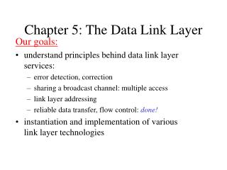
Topics • Toffoli gate • As a circuit element • A physical implementation • Quantum Error Correction • Bit-flip error correction • Phase-flip error correction
Introduction • Presence of noise requires error correction • General idea: • Toffoli gate for information recovery Add redundant information Noise Recover original information Informationto be preserved
The Toffoligate As a circuit element
Toffoligate or CCNOT gate |000> |001> |010> |011> |100> |101> |110> |111> |000> |001> |010> |011> |100> |101> |111> |110> 1 0 0 0 0 0 0 0 0 1 0 0 0 0 0 0 0 0 1 0 0 0 0 0 0 0 0 1 0 0 0 0 0 0 0 0 1 0 0 0 0 0 0 0 0 1 0 0 0 0 0 0 0 0 0 1 0 0 0 0 0 0 1 0 Circuit Symbol Matrix Representation Truth Table
CCPhase to CCNOT is equivalent to H H
The Toffoligate A physicalimplementation
A superconducting circuit Microwavetransmission line resonator 3 transmonqubits Fedorov, A.; Steffen, L.; Baur, M.; Wallraff A.Implementation of a Toffoli Gate withSuperconductingCircuitsarXiv:1108.3966 (2011)
Resonatorfeatures • Bareresonatorfrequency: νr = 8.625 GHz • Quality factor: Q = 3300 Transmission (dB) Frequency Fedorov, A.; Steffen, L.; Baur, M.; Wallraff A.Implementation of a Toffoli Gate withSuperconductingCircuitsarXiv:1108.3966 (2011)
Qubitfeatures • Somenumerical values: • Maximum transition frequencies: νA,B,C = {6.714, 6.050, 4.999} GHz • Chargingenergies: EC/h = {0.264, 0.296, 0.307} GHz • Couplingstrengths: g/2π = {0.36, 0.30, 0.34} GHz • Energyrelaxation time: T1 = {0.55, 0.70, 1.10} μs • Phase coherence time: T2*= {0.45, 0.6, 0.65} μs • Use states ⎢0〉, ⎢1〉 (computational states) and ⎢2〉 • anharmonicity En ng Fedorov, A.; Steffen, L.; Baur, M.; Wallraff A.Implementation of a Toffoli Gate withSuperconductingCircuitsarXiv:1108.3966 (2011)
Simplification of Toffoligate • Using quantum levels⎢0〉 and ⎢1〉: 6 CNOT gates and several single qubitoperations • Using quantum levels⎢0〉, ⎢1〉 and ⎢2〉: halfduration of precedentschemes Trick: hidequbit in the 3rd level
Circuit diagram • Aim: achieving⎢001〉 → - ⎢001〉 Red: « hide » the thirdqubit in non-computational state (π-SWAP and 3π-SWAP) Green: single qubit rotations Blue: CPHASE gate Fedorov, A.; Steffen, L.; Baur, M.; Wallraff A.Implementation of a Toffoli Gate withSuperconductingCircuitsarXiv:1108.3966 (2011)
Circuit diagram • Aim: achieving⎢001〉 → - ⎢001〉 Fedorov, A.; Steffen, L.; Baur, M.; Wallraff A.Implementation of a Toffoli Gate withSuperconductingCircuitsarXiv:1108.3966 (2011)
Rotating single qubits • Applymicrowave pulses • Frequencycontroled by flux pulses through the SQUID loop (few nanoseconds long)
CouplingQubits • Transmission line resonatorused as quantum bus • Microwave pulses
The SWAP gates • Qutrittunednon-adiabatically • Evolution: U ⎟11x〉 = cos(Jt) ⎟11x〉 – i sin(Jt) ⎟20x〉 • Choose t such as to performπ, 2π and 3πgates • Interaction times: t = { π, 2π, 3π } / 2J11,20 = { 7, 23, 20 } ns ⎜20x〉or ⎜x20〉 ν ⎜11x〉or ⎜x11〉 Φ/Φ0
The whole pulse sequence • Flux pulses • Microwave pulses Fedorov, A.; Steffen, L.; Baur, M.; Wallraff A.Implementation of a Toffoli Gate withSuperconductingCircuitsarXiv:1108.3966 (2011)
The Toffoligate Performance Evaluation
Fidelity and total gate time Fidelity of the measured truth table: F=(1/8)TR[UexpT Uideal]=76% Total gate time: 90 ns Fedorov, A.; Steffen, L.; Baur, M.; Wallraff A.Implementation of a Toffoli Gate withSuperconductingCircuitsarXiv:1108.3966 (2011)
Full Process Tomography • Include non classical features of the Toffoli gateF=Tr[χexptχideal] =69% Fedorov, A.; Steffen, L.; Baur, M.; Wallraff A.Implementation of a Toffoli Gate withSuperconductingCircuitsarXiv:1108.3966 (2011)
About quantum error correction codes • Classicalidea: make the input signal redundant • Detect an errorwithoutmeasuring the actual state • correct witoutdestroyingcoherence • Correct errors on ONE qubitonly
Quantum Error Correction Bit-flip Correction
Bit flip correction • Correct errors of type σX|Ψ〉(σX Pauli operator) Bit-flip errors |0> |Ψ> |0> 4 1 2 3 Initial state: Qubit 1: |0〉Qubit 2: α|0〉 + β|1〉Qubit 3: |0〉 3-qubit-state: α|000〉 + β|010〉 Reed, M. D; DiCarlo, L.; Nigg, S. E; et al.Realization of Three-Qubit Quantum Error CorrectionwithSuperconductingCircuitsarXiv:1109.4948 (2011)
Bit flip correction • Correct errors of type σX|Ψ〉(σX Pauli operator) Bit-flip errors |0> |Ψ> |0> 4 1 2 3 Entanglement: α |000> + β |111> Reed, M. D; DiCarlo, L.; Nigg, S. E; et al.Realization of Three-Qubit Quantum Error CorrectionwithSuperconductingCircuitsarXiv:1109.4948 (2011)
Bit flip correction • Correct errors of type σX|Ψ〉(σX Pauli operator) Bit-flip errors |0> |Ψ> |0> 4 1 2 3 Bit flip withprobability p: Divenby rotation angle θ introducedby y-rotation (p=sin2(θ/2)) Reed, M. D; DiCarlo, L.; Nigg, S. E; et al.Realization of Three-Qubit Quantum Error CorrectionwithSuperconductingCircuitsarXiv:1109.4948 (2011)
Bit flip correction • Correct errors of type σX|Ψ〉(σX Pauli operator) Bit-flip errors |0> |Ψ> |0> 4 1 2 3 Reverse process: « desantanglement » α|000〉 + β|010〉 If no erroroccured! Reed, M. D; DiCarlo, L.; Nigg, S. E; et al.Realization of Three-Qubit Quantum Error CorrectionwithSuperconductingCircuitsarXiv:1109.4948 (2011)
Bit flip correction • Correct errors of type σX|Ψ〉(σX Pauli operator) Bit-flip errors |0> |Ψ> |0> 4 1 2 3 Toffoligate: Correction if and only if the twoancillaqubits are in an excited state Reed, M. D; DiCarlo, L.; Nigg, S. E; et al.Realization of Three-Qubit Quantum Error CorrectionwithSuperconductingCircuitsarXiv:1109.4948 (2011)
Quantum Error Correction Phase-flip Correction
Phase Errors • Phase errors are errors of the form Z |ψ> (Z is Pauli operator) • Errors with probability p are modeled by Z-gates with known rotation angle θ with p=sin2(θ/2) • Projecting the systems state onto the possible error syndromes causes the system to „decide“ if a full phase flip error occured or not
Phase Error Correction Circuit Phase errors H H |0> H H |Ψ> H H |0> 6 5 1 2 3 4 Initial state: Qubit 1: |0> Qubit 2: α|0> + β|1> Qubit 3: |0> 3-qubit-state: α|000> + β|010> Reed, M. D; DiCarlo, L.; Nigg, S. E; et al.Realization of Three-Qubit Quantum Error CorrectionwithSuperconductingCircuitsarXiv:1109.4948 (2011)
Phase Error Correction Circuit Phase errors H H |0> H H |Ψ> H H |0> 6 5 1 2 3 4 After two CNOT operations: α |000> + β |111> Reed, M. D; DiCarlo, L.; Nigg, S. E; et al.Realization of Three-Qubit Quantum Error CorrectionwithSuperconductingCircuitsarXiv:1109.4948 (2011)
Phase Error Correction Circuit Phase errors H H |0> H H |Ψ> H H |0> 6 5 1 2 3 4 Changing the basis to |+>=1/sqrt(2)(|0>+|1>) |–>=1/sqrt(2)(|0>–|1>) results in: α |+ + +> + β |– – –> Reed, M. D; DiCarlo, L.; Nigg, S. E; et al.Realization of Three-Qubit Quantum Error CorrectionwithSuperconductingCircuitsarXiv:1109.4948 (2011)
Phase Error Correction Circuit Phase errors H H |0> H H |Ψ> H H |0> 6 5 1 2 3 4 If a relative phase error of π is inserted on the second qubit, the 3-qubit-state gets: α |+ – +> + β |– + –> And after returning to the original basis: α |010> + β |101> Reed, M. D; DiCarlo, L.; Nigg, S. E; et al.Realization of Three-Qubit Quantum Error CorrectionwithSuperconductingCircuitsarXiv:1109.4948 (2011)
Phase Error Correction Circuit Phase errors H H |0> H H |Ψ> H H |0> 6 5 1 2 3 4 Again after two CNOT operations: α |111> + β |101> Applying a CCNOT operation on the second qubit results in: α |101> + β |111> Thus the ancilla qubits are now both |1> and the second qubit is in its original state |Ψ>= α|0> + β|1> Reed, M. D; DiCarlo, L.; Nigg, S. E; et al.Realization of Three-Qubit Quantum Error CorrectionwithSuperconductingCircuitsarXiv:1109.4948 (2011)
ProcessFidelity f=(0.76±0.005) – (1.46±0.03)p2 + (0.72±0.03)p3 Since the code corrects only single qubit errors, it will fail, for two or more errors. -> linear dependence on p suppressed! Reed, M. D; DiCarlo, L.; Nigg, S. E; et al.; Realization of Three-Qubit Quantum Error CorrectionwithSuperconductingCircuitsarXiv:1109.4948 (2011)
What to remember • Codes to detect and correct errorswithoutdestroyingcoherence • Implemented in superconductor circuits, usingToffoligate • Use an interaction with the thirdexcited state
Sources • Fedorov, A.; Steffen, L.; Baur, M.; Wallraff A.Implementation of a Toffoli Gate with Superconducting Circuits arXiv:1108.3966 (2011) • Reed, M. D; DiCarlo, L.; Nigg, S. E; et al.Realization of Three-Qubit Quantum Error Correction with Superconducting CircuitsarXiv:1109.4948 (2011)
Outlook • Shor code: protects against arbitrary error on a single qubit • To be presented by Dezeure Ruben & Schneider Manuel on Dec 19