Data Conversion
Slides by Prof. Brian L. Evans, Dept. of ECE, UT Austin, and Dr. Thomas D. Kite, Audio Precision, Beaverton, OR tomk@audioprecision.com Dr. Ming Ding, when he was at the Dept. of ECE, UT Austin, converted slides by Dr. Kite to PowerPoint format

Data Conversion
E N D
Presentation Transcript
Slides by Prof. Brian L. Evans, Dept. of ECE, UT Austin, and Dr. Thomas D. Kite, Audio Precision, Beaverton, OR tomk@audioprecision.com Dr. Ming Ding, when he was at the Dept. of ECE, UT Austin, converted slides by Dr. Kite to PowerPoint format Some figures are from Ken C. Pohlmann, Principles of Digital Audio, McGraw-Hill, 1995. Data Conversion
Image Halftoning • Handout J on noise-shaped feedback coding Different ways to perform one-bit quantization (halftoning) Original image has 8 bits per pixel original image (pixel values range from 0 to 255 inclusive) • Pixel thresholding: Same threshold at each pixel Gray levels from 128-255 become 1 (white) Gray levels from 0-127 become 0 (black) • Ordered dither: Periodic space-varying thresholding Equivalent to adding spatially-varying dither (noise)at input to threshold operation (quantizer) Example uses 16 different thresholds in a 4 4 mask Periodic artifacts appear as if screen has been overlaid No noise shaping No noise shaping
Image Halftoning • Error diffusion: Noise-shaping feedback coding Contains sharpened original plus high-frequency noise Human visual system less sensitive to high-frequency noise (as is the auditory system) Example uses four-tap Floyd-Steinberg noise-shaping(i.e. a four-tap IIR filter) • Image quality of halftones Thresholding (low): error spread equally over all freq. Ordered dither (medium): resampling causes aliasing Error diffusion (high): error placed into higher frequencies • Noise-shaped feedback coding is a key principle in modern A/D and D/A converters
Digital Halftoning Methods Clustered Dot Screening AM Halftoning Dispersed Dot Screening FM Halftoning Error Diffusion FM Halftoning 1975 Blue-noise MaskFM Halftoning 1993 Green-noise Halftoning AM-FM Halftoning 1992 Direct Binary Search FM Halftoning 1992
Screening (Masking) Methods • Periodic array of thresholds smaller than image Spatial resampling leads to aliasing (gridding effect) Clustered dot screening produces a coarse image that is more resistant to printer defects such as ink spread Dispersed dot screening has higher spatial resolution
Error DiffusionHalftone 7/16 3/16 5/16 1/16 Spectrum Grayscale Error Diffusion • Shapes quantization error (noise)into high frequencies • Type of sigma-delta modulation • Error filter h(m) is lowpass current pixel difference threshold u(m) + x(m) b(m) _ _ + e(m) weights shapeerror (noise) compute error (noise) Floyd-Steinberg filter h(m)
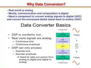
Analog Lowpass Filter Quantizer Sampler at sampling rate of fs Discrete to Continuous Conversion Analog Lowpass Filter Old-Style A/D and D/A Converters • Used discrete components (before mid-1980s) • A/D Converter Lowpass filter hasstopband frequencyof ½ fs • D/A Converter Lowpass filter hasstopband frequencyof ½ fs Discrete-to-continuousconversion could be assimple as sample and hold fs
A B C D Cost of Multibit Conversion Part I:Brickwall Analog Filters Pohlmann Fig. 3-5 Two examples of passive Chebyshev lowpass filters and their frequency responses. A. A passive low-order filter schematic. B. Low-order filter frequency response. C. Attenuation to -90 dB is obtained by adding sections toincrease the filter’s order. D. Steepness of slope and depth of attenuation are improved.
Cost of Multibit Conversion Part II:Low- Level Linearity Pohlmann Fig. 4-3 An example of a low-level linearity measurement of a D/A converter showing increasing non-linearity with decreasing amplitude.
Solutions • Oversampling eases analog filter design Also creates spectrum to put noise at inaudible frequencies • Add dither (noise) at quantizer input Breaks up harmonics (idle tones) caused by quantization • Shape quantization noise into high frequencies Auditory system is less sensitive at higher frequencies • State-of-the-art in 20-bit/24-bit audio converters Oversampling 64x 256x 512x Quantization 8 bits 6 bits 5 bits Additive dither 2-bit PDF 2-bit PDF 2-bit PDF Noise shaping 5th / 7th order 5th / 7th order 5th / 7th order Dynamic range 110 dB 120 dB 120 dB
Solution 1: Oversampling A. A brick-wall filter must sharply bandlimit the output spectra. B. With four-times oversampling, images appear only at the oversampling frequency. C. The output sample/hold (S/H) circuit can be used to further suppress the oversampling spectra. Pohlmann Fig. 4-15 Image spectra of nonoversampled and oversampled reconstruction.Four times oversampling simplifies reconstruction filter.
Solution 2: Add Dither Pohlmann Fig. 2-8 Adding dither at quantizer input alleviates effects of quantization error.A. An undithered input signal with amplitude on the order of one LSB.B. Quantization results in a coarse coding over two levels. C. Dithered input signal.D. Quantization yields a PWM waveform that codes information below the LSB.
Time Domain Effect of Dither A A 1 kHz sinewave with amplitude of one-half LSB without dither produces a square wave. C Modulation carries the encoded sinewave information, as can be seen after 32 averagings. B Dither of one-third LSB rms amplitude is added to the sinewave before quantization, resulting in a PWM waveform. D Modulation carries the encoded sinewave information, as can be seen after 960 averagings. Pohlmann Fig. 2-9 Dither permits encoding of information below the least significant bit. Vanderkooy and Lipshitz.
undithered undithered dithered dithered Frequency Domain Effect of Dither Pohlmann Fig. 2-10 Computer-simulated quantization of a low-level 1- kHz sinewave without, and with dither. A. Input signal. B. Output signal (no dither). C. Total error signal (no dither). D. Power spectrum of output signal (no dither). E. Input signal. F. Output signal (triangualr pdf dither). G. Total error signal (triangular pdf dither). H. Power spectrum of output signal (triangular pdf dither)Lipshitz, Wannamaker, and Vanderkooy
added noise Adder Inputs OutputTime Upper Lower Sum to DAC 1 1001 00 1001 10 2 1001 01 1010 10 3 1001 10 1011 10 4 1001 11 1100 11 12 dB (2 bits) f If signal is in this band, you are better off! Let’s hope this is above the passband! (oversample) Periodic Average output = 1/4(10+10+10+11)=1001 4-bit resolution at DC! Solution 3: Noise Shaping We have a two-bit DAC and four-bit input signal words. Both are unsigned. Inputsignal words 4 2 Going from 4 bits down to 2 bits increases noise by ~ 12 dB. However, the shaping eliminates noise at DC at the expense of increased noise at high frequency. ToDAC 2 2 1 sample delay Assume input = 1001 constant
Putting It All Together • A/D converter samples at fs and quantizes to B bits • Sigma delta modulator implementation Internal clock runs at Mfs FIR filter expands wordlength of b[m] to B bits dither x(t) v[m] x[m] b[m] + Sample and hold FIR Filter M _ quantizer _ Mfs + e[m]