Download
1 / 21
210 likes | 237 Views
Learn about circuit theory, including voltage, current, power, and energy in electric circuits. Understand reference directions, passive sign convention, and mathematical models of circuit components.

E N D
Keypoints Circuit theory 1.1 Voltage and Current 1.2 Power and Energy 1.3 Chapter 1Circuit Variables
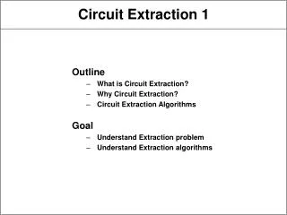
Back • Key Points: 1. Reference direction of Voltage and Current 2. Power calculation
1.1 Electric Circuit Model 1.Actual Circuit 由电工设备和电气器件按预期目的连接构成的电流的通路。 a The transfer, distribute and transform of Energy; b The transfer, control and process of Signals。 Function Character in Common Based on the same Electric Circuit theory。
Switch Bulb Battery Wire 上 页 下 页 返 回 Circuit Model 2. Circuit Model Mathematical model of the actual circuit, approximates the main character of actual circuit • Circuit Model Mathematical model of an actual component, can represent the behavior to a acceptable degree of accuracy。 • Ideal Circuit Components
Attention The Ideal Basic Circuit Element: Resistor:consume electric power Inductor:generate magnetic field,save magnetic power. Capacitor:generate Electric field,save electric power. Voltage source and Current Source:transform other kinds of power into electrical power. Three Attributes of ideal basic circuit element: (a)Only two terminals; (b)It can be described mathematically in terms of current and/or Voltage; (c)It cannot be subdivided into other elements。
Attention Different actual components which have the same Electro-Magnetic character, can be represent by the same Ideal circuit Element in some case; One actual components, should be represent by different ideal circuit element in different case; Example The model of Actual Inductor coil
上 页 下 页 返 回 1.2 Reference Direction of Voltage and Current Circuit theory concern about several variables: Voltage, Current, Charges, Magnetic Intensity Power and Energy。 1.Refrence direction of Current • Current The flow of Electric Charges • Current Intensity The rate of charges flow
Actual direction A B Actual direction A B Problem 1kA=103A 1mA=10-3A 1 A=10-6A • SI A(Amper)、kA、mA、A • Direction The direction of Positive Charges The actual direction in element or Wire have two possibilities: In some complicate circuit, or the circuit in which current change with time, it’s difficult to judge the actual direction。
Current(Algebraic variable) iReference direction Amplitude A B Direction(Positive and Negative) iReference direction iReference direction A B A B Indicate • Reference Direction Assume one direction free。 The relation between reference direction and actual direction: Actual direction Actual direction i < 0 i > 0
iReference direction A B iAB A B Two Expression of Current direction By Arrow: By Subscript:Such asiAB, The current reference direction is flow from A to B。
2.Voltage Reference Direction The energy that electrical force created on the charge qfrom one point to the reference point(=0)。 • Electrical Potential The energy that electrical force created on the charge qfrom one point to another point。 • ValtageU • Actual Voltage direction The direction of Potential decrease。 • SI V (Volt)、kV、mV、V
b a c • Known:4Cpositive charges move from Point a to b, the electrical force created energy 8J ,created 12J from b to c. • Assume the point b is reference point,Find Potential of a、b、c, and voltage of Uab、U bc; • Assume the point c is reference point, Please caculate the variables again Example Solution (1)
b a c Conclusion Solve (2) The reference point can be assumed freely. When the reference point assumed, the potential will be determined The potential will changed with the reference point,but the voltage between two point will never changed with the reference point。
Reference Direction U Reference direction U – + – + – – + + Actual direction Actual direction U < 0 Problem U > 0 In complicate circuit or circuit that voltage change with time, the actual voltage direction is difficult to judge 。 From high potential to low potential。 • Voltage Reference Direction
B A 上 页 下 页 返 回 Three expression method of Voltage Direction: (1) By Arrow: U (2)By Positive and Negative U + (3)BySubscript UAB
3.Passive Sign Convention The component use the same reference direction of u,I。 i i + - + - u u Passive Sign Convention Non Passive Sign Convention
i + u A B Attention - Example The voltage and current direction is as the figure shown ,question:is it passive sign convention for A and B Answer:Part ANon Passive Sign Convention ; Part B, Passive Sign Convention。 • Assume the Voltage and Current direction before Analyze. • Can’t change the direction in your analyze process • When choose different reference direction, the answer will be different polarity, but the actual direction will be the same。
1.3 Power and Energy 1.Power Energy per Unit time Power SI:W (瓦) (Watt,瓦特) Energy SI:J (焦) (Joule,焦耳)
+ u i - - u i + 2. The judge of delivered of extract power from component • u, i use passive sign convention P=uidelivered to element P>0absorb positive power(actual absorb) P<0absorb negative power(actual release) • u, iuse non passive sign convention P = uiextract from element P>0Release positive power(actual release) P<0Release negative power(actual absorb)
U1 U6 + - - + 1 6 I1 - + + 4 5 U5 U4 2 U2 - + - I3 I2 U3 + - 3 上 页 返 回 下 页 Example Caculate the part power, point out absorb or release。 Known: U1=1V, U2= -3V,U3=8V, U4= -4V, U5=7V, U6= -3V,I1=2A, I2=1A,,I3= -1A
U1 U6 + - - + 1 6 I1 - + + 4 5 U5 U4 2 U2 - + - I3 I2 U3 + - 3 Attention Solution For a complicate circuit:Absorbed power=Released Power Conservation-of-Energy Principles