Download
1 / 47
510 likes | 694 Views
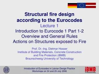
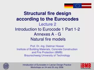
Structural fire design according to the Eurocodes Lecture 2 Introduction to Eurocode 1 Part 1-2 Annexes A - G Natural fire models. Prof. Dr.-Ing. Dietmar Hosser Institute of Building Materials, Concrete Construction and Fire Protection (iBMB) Braunschweig University of Technology. Lecture 2.

E N D
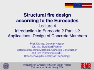
Structural fire designaccording to the EurocodesLecture 2Introduction to Eurocode 1 Part 1-2Annexes A - G Natural fire models Prof. Dr.-Ing. Dietmar Hosser Institute of Building Materials, Concrete Constructionand Fire Protection (iBMB) Braunschweig University of Technology
Lecture 2 • General background • Performance-based fire safety engineering • Procedures and necessary information • Informative Annexes A to G • Overview • Parametric temperature-time curves (A) • Thermal actions for external members (B) • Localised Fires (C) • Advanced fire models (D) • Fire load densities (E) • Equivalent time of fire exposure (F) • Configuration factor (G) • Discussion
Prescriptive versus Performance-based design prescriptive Basic data and boundary conditionsof the building Fire protction requirements of the Building Code Passive fire protection measures Specification of the use and the number of users Fire protection systems andactive fire protection measures Definition of safety objectives and related criteria Determination of fire loads,definition of design fires conventionaldesign Verification of safety Modification / Compensation of passive measures Safety of the construction ? Requirementsfulfilled? Safety of the users? no yes Safety of installations etc.? no Design accepted Safety objectives fulfilled? yes
Alternative Design Procedures Level 2 Level 3 Prescriptive Rules defined in EC 1-1-2 sec. 3.2, required time period takenfrom national regulations Nominal Fire Mechanical Actions Member Entire Structure Part of the Structure Level 1 Level 3 Level 2 Level 3
Prescriptive versus Performance-based design Basic data and boundary conditionsof the building Fire protction requirements of the Building Code Passive fire protection measures Specification of the use and the number of users Fire protection systems andactive fire protection measures Definition of safety objectives and related criteria Determination of fire loads,definition of design fires conventionaldesign Verification of safety Modification / Compensation of passive measures fire safety engineering performance-based Safety of the construction ? Eurocodes Requirementsfulfilled? Safety of the users? no yes Safety of installations etc.? no Design accepted Safety objectives fulfilled? yes
Alternative Design Procedures compartment fire external fire localised fire Level 2 Level 3 Performance-based Code only principles given in EC 1-1-2 sec. 3.3; more details in inform. Annexes Simple or Advanced Fire Development Model Mechanical Actions Part of the Structure Entire Structure Member complete fire scenario Level 3 Level 3
Natural Fire Models • Annex A Parametric temperature-time curves • General background • Fire scenario and assumptions • Annex B Thermal actions for external members • Size and temperatures of the flames from openings • Effects of wind, forced draught, balconies • Annex C Localised fires • Empircal equations for temperatures above the fire source • Plume and Ceiling Jet considered • Annex D Advanced fire models • One-Zone-Model • Two-Zone-Model • CFD-Model
Natural Fire Models • Annex E Fire load densities • General background • Fire load densities for different occupancies • Partial safety factors depending on measures for fire protection • Rate of heat release for different occupancies • Annex F Equivalent time of fire exposure • Proposed for design of members related to standard fire exposure • Correction depending on the material of the member • Annex G Configuration factor • Fraction of the total radiative heat between radiating an receiving surfaces • Proposed for members in localised fires and/or external members
Parametric Temperature-Time Curves • Fire compartments 500 m2 floor area and 4 m height • Fire load completely burnt out • Vertical ventilation openings with total area Av and average height heq opening factor O [m1/2] • Boundary of enclosure with thermal properties density , specific heat c, thermal conductivity
Parametric Temperature-Time Curves • Maximum temperature in the heating phase depending on ventilation conditions and fire load • ventilation controlled fire (combustion limited by ventilation rate) tmax depending on the design fire load densityqt,d related to the total surface area At of the enclosure • fuel controlled fire (enough oxygen for complete combustion)tlim = 25 min for slow growth rate 20 min for medium growth rate 15 min for fast growth rate
Parametric Temperature-Time Curves 1200 40 1000 30 Temperature test NFSC 800 Temperature EN 1991 Temperature [°C] Heat release rate EN 1991-1-2, Annex E 600 20 Heat release rate [MW] 400 10 200 tlim tlim ? 0 0 0 10 20 30 40 50 60 (Annex A) Time [min]
Parametric Temperature-Time Curves Alternative proposal for Germany 1200 7.5 Hot gas temperature T 2 Heat release rate 70% of the fire load 1000 6.25 · Q consumed max T 1 800 5 Temperature [°C] 600 3.75 T Heat release rate [MW] 3 400 2.5 200 1.25 0 0 t t t 0 15 30 45 60 75 90 105 120 135 150 165 180 1 2 3 Time [min]
Parametric Temperature-Time Curves Alternative proposal for Germany 1400 q = 1300 MJ/m2 1200 1/2 T=(T -T )*((t-t )/(t -t )) +T 2 1 1 2 1 1 (t /T ) for t <=t<=t 2 2 1000 1 2 1/2 T=(T -T )*((t-t )/(t -t )) +T 3 2 2 3 2 2 800 for t>=t Temperature [°C] 2 (t /T ) 1 1 600 (t /T ) 3 3 400 T= (T -T )/t ²*t²+T 1 0 1 0 200 for t<=t 1 (t /T ) 0 0 0 range 3 0 15 30 45 60 75 90 105 120 135 150 165 180 range 1 range 2 Time [min]
Parametric Temperature-Time Curves 1200 T 2 T 2,900 1000 T 2,500 1300 MJ/m² 900 MJ/m² T - 800 1 500 MJ/m² T =(T /log (t +1))*log (t+1) 3,x 3 10 3 10 Temperature [°C] T 600 3 T 3,900 T 3,500 400 200 0 t t t t t t t 0 15 30 45 60 75 90 105 120 135 150 165 180 1 2,500 2 3,900 3 2,900 3,500 Time [min]
Comparison with Zone-Models 1600 b= 500 b= 1000 1400 b= 1500 1200 b= 2000 b= 2500 1000 Temperature [°C] 800 600 T = 33000 k +20 2 400 200 0 0 0.01 0.02 0.03 0.04 0.05 k [-]
Comparison with Zone Models 1200 Natural fire curve 1000 CFAST 800 Temperature [°C] 600 measured hot gas temp. 400 OZONE 200 0 0 10 20 30 40 50 60 Time [min]
Comparison with Test Results 1400 Natural fire curve (RBK) OZONE (OZ) 1200 [EN1991-1-2] (EC) 1000 [FEA02] (FE) [ZHO00] (ZH) 800 [BAR02] (BA) Temperature calculation (cal T) [°C] +15 % 600 400 cal T / exp T RBK OZ EC FE ZH BA -15 % mean 0,99 0,80 0,93 1,01 0,91 0,90 200 maximum 1,17 1,01 1,22 1,28 1,11 1,08 minimum 0,89 0,66 0, 78 0,87 0,48 0,69 0 0,08 0,09 0,1 2 0,12 0,15 0,12 stand. dev. 0 200 400 600 800 1000 1200 1400 Temperature experiment (exp T) [°C]
Thermal Action for External Members Results from large scale fire tests Y [m] perpendicular to the facade (Annex B) X [m] parallel to the facade
Thermal Action for External Members • Fully developed fire in the compartment • heat release rate Q and • temperature f inside the compartment • Geometry of the flame • flame height LL • horizontal projection of the flame LH • flame length along the axis Lf • Temperature field outside the window(s) • sum of the widths wt and average height heq of the windows • temperature along the axis z
Special Effects • Effects of wind • deflection of the flame perpendicular to the facade due to wind perpendicular to the facade • with an angle of 45° due to wind parallel to the facade • Effect of a balcony or awning • modified flame height and horizontal projection • Forced draught conditions • air velocity u [m/s] • modified flame length and flame temperature • Radiative heat transfer from openings • heat transfer from the flame:overall configuration factor f • heat transfer from a window:overall configuration factor z
Special Effects with balcony or awning with forced draught normal situation
Design Aids + z w Proposal for Germany
Localised Fires velocity and temperature profile entrainment 2 / 3 Plume equation: (Annex C)
Plume Temperatures plume ceiling Z (m) plume,m plume plume H1 z plume,m max T (°C)
Localised Fires ceiling jet plume entrainment H1 15° flame fire source (Annex C)
Comparison with Tests Natural fire test in a 6000 m² hangar with different fire loads (heptane and wood) within the European NFSC2 project 800 calculation 700 test 600 500 400 Average temperature of the plume [°C] 300 200 Comparison of the plume temperatures 3 m above the fire source 100 0 0 2 4 6 8 10 12 14 16 18 Time [min]
Example temperature of the ceiling jet (steel gírder);no protection needed average temperature of the plume in 4 m heigth (steel column)protection R 30 needed up to 5 m heigth critical temperature
Advanced Fire Models • One-Zone model • Two-Zone model • Vertical subdivision of the compartment in a hot gas layer and a cold gas layer • With multiple room modelling horizontal subdivision in different segments • CFD model • Vertical and horizontal subdivision in small volume elements • Solving the differential equation for mass, energy and impulse conservation on the space grid (time-consuming)
One-Zone-Model whole fire compartment as control volume
Two-Zone-Model hot gas layer entrainment H1 plume cold gas layer 15° flame (Annex D) fire source
CFD Model Muster freie Randbedingungen 5 4 3 z 2 1 0 0 1 2 3 4 5 6 7 8 9 10 x = 2,00m/s Strömungsgeschwindigkeit v: y=1,70 m; t=30,0s air velocity v flexible discretisation as fine as necessary
Comparison with Large-Scale Fire Tests Test building in Laue Fire compartment with fire source (pool fire)
Two-Zone Model MRFC
CFD Model KOBRA-3D FLUENT
CFD Model FDS
Conclusion • Advantages • Simulation of a realistic natural fire with (all) relevant fire effects • Basis for a realistic determination of load bearing and deformation behaviour of structures real failure time • Appropriate for parameter variations • Disadvantages • More advanced model are very time-consumin • Background information and knowledge is needed • Choice of input parameters needs experience • Not every structural problem can be solved (influence of structural detailing)
Fire Load Densities A = either floor area Af or inner surface area At Tab. E.4
Safety Concept Design value of fire load density factor for fire activation risk due to compartment size factor for fire activation risk due to occupancy factor for reduction of risk due to active measures = 1,10 .... 2.13 = 0.78 .... 1.66 = 0.61 ... 1.5 • Problems • Different parameters for active measures are not independent • Probabilities of occurrence of a fire cannot be calculated by multiplication of factors ni
Heat Release Rate 12 10 . · 70% of the fire load Q consumed max 8 Heat release rate [MW] 6 4 2 0 0 10 20 30 40 50 60 70 80 90 100 (Annex E) Time [min] (ventilation controlled) (fuel controlled)
Heat Release Rate Growing phase of the fire with t = time needed to reach Q = 1 MW
Equivalent Time of Fire Exposure Nominal fire Natural fire Temperature of reinforcement Temperature [°C] Temperature ofreinforcement te Time [min]
Equivalent Time of Fire Exposure Empirical relation Empirical relation wt = ventilation factor for small compartments without openings in the roof = O-1/2 At / Af kb = conversion factor (thermal properties of the enclosure = 0.04 ... 0.07 kc = correction factor (different construction materials = 1.0 for reinf. Concrete and protected steel = 13.7 O for unprotected steel
Configuration Factor Receiving surface parallel to the radiating surface Receiving surface perpendicular to the radiating surface
Nationally Determined Parametes (NDP) 2.4 (4) basis for the period of time for nominal fire curve 3.1 (10) definition of the gas temperature as nominal temperature-time curve or according to fire models 3.3.1.1 (1) use of simple fire models with field of application 3.3.1.2 (1) procedure for calculating heating conditions for compartment fires (cf. Appendix A) 3.3.1.2 (2) procedure for calculating heating conditions for external fires (cf. Appendix B) 3.3.1.3 (1) procedure for calculating heating conditions for localised fires (cf. Appendix C) 3.3.2 (1) procedure for defining fire load density and heat release rate (cf. Appendix E)
Nationally Determined Parametes (NDP) 3.3.2 (2) procedure for calculating heating conditions of natural fires (cf. Appendix D) 4.2.2 (2) definition of additional actions induced by the fire 4.3.1 (2) definition of variable actions with frequent or quasi-permanent values