Download
1 / 20
480 likes | 1.25k Views
Optical Multiplexing & Demultiplexing:. optical telecommunication networks. Phillip B. Oni (u96761) AUTO3160 – OPTICS & SPECTROSCOPY VAASA, Spring 2012. Outline. Introduction Multiplexing / Demultiplexing Optical Multiplexing Components of Optical Mux/Demux Application Advantages

E N D
Optical Multiplexing & Demultiplexing: optical telecommunication networks Phillip B. Oni (u96761) AUTO3160 – OPTICS & SPECTROSCOPY VAASA, Spring 2012.
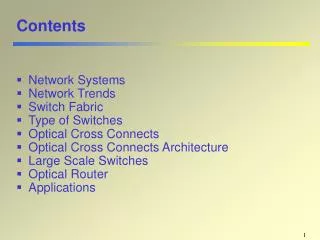
Outline Introduction Multiplexing / Demultiplexing Optical Multiplexing Components of Optical Mux/Demux Application Advantages Shortcomings/Future Work Conclusion References
Introduction Optical transmission uses pulses of light to transmit information from one place to another through an optical fiber. The light is converted to electromagnetic carrier wave, which is modulated to carry information as the light propagates from one end to another. The development of optical fiber has revolutionized the telecommunications industry. Optical fiber was first developed in the 1970s as a transmission medium. It has replaced other transmission media such as copper wire since inception, and it’s mainly used to wire core networks. Today, optical fiber has been used to develop new high speed communication systems that transmit information as light pulses, examples are multiplexers.
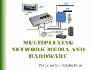
Multiplexing & Demultiplexing • Multiplexing • What are Multiplexers? • Multiplexers are hardware components that combine multiple analog or digital input signals into a single line of transmission. • And at the receiver’s end, the multiplexers are known as de-multiplexers – performing reverse function of multiplexers. • Multiplexing is therefore the process of combining two or more input signals into a single transmission. • At receiver’s end, the combined signals are separated into distinct separate signal. • Multiplexing enhances efficiency use of bandwidth.
Multiplexer http://en.wikipedia.org/wiki/File:Telephony_multiplexer_system.gif
Multiplexing Example • MATLAB simulation example: • Sampled in time: • Quantization • Digitization
Multiplexing Example • Multiplexed Signals • Separation of signals • Using time slots.
Laser 1 Laser 2 Multiplexer Optical Fiber De-multiplexer Laser 3 Laser 4 Regenerator + Receiver Optical Multiplexing Optical multiplexer and de-multiplexer are required to multiplex and de-multiplex various wavelengths onto a single fiber link. Each specific I/O will be used for a single wavelength. One optical filter system can act as both multiplexer and de-multiplexer
Optical Multiplexing • Optical multiplexer and de-multiplexer are basically passive optical filter systems, which are arranged to process specific wavelengths in and out of the transport system (usually optical fiber). • Process of filtering the wavelengths can be performed using: • Prisms • Thin film filter • Dichroic filters or interference filters • The filtering materials are used to selectively reflect a single wavelength of light but pass all others transparently. • Each filter is tuned for a specific wavelength
Optical Multiplexing and Filtering Credit: [LYNX Technik Inc.www.lynx-technik.com]
Components of Optical Multiplexer • Combiner • Tap Coupler • ADD/DROP • Filters • Prisms • Thin film • Dichroic • Splitter • Optical fiber Credit: [LYNX Technik Inc.www.lynx-technik.com]
Optical Multiplexing Techniques • There are different techniques in multiplexing light signals onto a single optical fiber link. • Optical Multiplexing Techniques • Optical Time Division Multiplexing (OTDM) • Separating wavelengths in time • Wavelength division multiplexing (WDM) • Each channel is assigned a unique carrier frequency • Channel spacing of about 50GHz • Coarse Wavelength Division Multiplexing (CWDM) • Dense Wavelength Division Multiplexing • Uses a much narrower channel spacing, therefore, many more wavelengths are supported. • Code Division Multiplexing • Also used in microwave transmission. • Spectrum of each wavelength is assigned a unique spreading code. • Channels overlap both in time and frequency domains but the code guide each wavelength.
Applications The major scarce resource in telecommunication is bandwidth – users want transmit at more high rate and service providers want to offer more services, hence, the need for a faster and more reliable high speed system. Reducing cost of hardware, one multiplexing system can be used to combine and transmit multiple signals from Location A to Location B. Each wavelength, λ, can carry multiple signals. Mux/De-Mux serve optical switching of signals in telecommunication and other field of signal processing and transmission. Future next generation internet.
Advantages • High data rate and throughput • Data rates possible in optical transmission are usually in Gbps on each wavelength. • Combination of different wavelengths means more throughput in one single communication systems. • Low attenuation • Optical communication has low attenuation compare to other transport system. • Less propagation delay • More services offered • Increase return on investment (ROI) • Low Bit Error Rate (BER)
Shortcomings • Fiber output loss + dispersion • Signal is attenuated by fiber loss and distorted by fiber dispersion • Then regenerator are needed to recover the clean purposes • Inability of current Customer Premises Equipment (CPEs) to receive at the same transmission rate of optical transmitting systems. • Achieving all-optical networks • Optical-to-Electrical conversion overhead • Optical signals are converted into electrical signal using photo-detectors, switched and converted back to optical. • Optical/electrical/optical conversions introduce unnecessary time delays and power loss. • End-to-end optical transmission will be better.
Future Work • Research in optical end user equipment • Mobile phones, PC, and other handheld devices receiving and transmitting at optical rate. • Fast regeneration of attenuated signal • Less distortion resulting from fiber dispersion. • End-to-end optical components • Eliminating the need for Optical-to-Electrical converter and vise versa.
Conclusion • Optical multiplexing is useful in signal processing and transmission. • Transporting multiple signals using one single fiber link • The growth of the internet requires fiber optic transmission to achieve greater throughput. • Optical multiplexing is also useful in image processing and scanning application. • Optical transmission is better compare to other transmission media because of its low attenuation and long distance transmission profile.
THANK YOU KIITOS
References Russell Steve. (2010) “The CWDM Fiber Primer” LYNX Technik Inc. <www.lynx-technik.com> 8/05/2012 Indumathi. T. S et al. (2009) "Evaluating Wavelength Routing Power of Dynamic ROADM Networks (cat-I)" International Conference on Advanced Information Networking and Applications Workshop. SalehBahaa E. A., Malvin Carl Teich. (1991) Fundamentals of photonics. Wiley: New York. pg 799 – 832 Watanabe, Shigeki. (2012) "All-Optical Data Frequency Multiplexing on Single-Wavelength Carrier Light by Sequentially Provided Cross-Phase Modulation in Fiber." IEEE Journal of Selected Topics in Quantum Electronics, Vol. 18, No. 2. Deng Lei. et al. (2012) "Fiber Wireless Transmission of 8.3 Gb/s/chQPSK-OFDM Signals in 75-110-GHz Band." IEEE Photonics Technology Letters, Vol. 24, NO. 5