A Scalable Content Addressable Network (CAN)
240 likes | 383 Views
A Scalable Content Addressable Network (CAN) . Sylvia Ratnasamy , Paul Francis, Mark Handley, Richard Karp, and Scott Shenker . 2001 Presented by Alex Gorohovski and Ilya Mirski. Yes, we CAN. The general problem. We want to provide files by requests at some net

A Scalable Content Addressable Network (CAN)
E N D
Presentation Transcript
A Scalable Content AddressableNetwork (CAN) Sylvia Ratnasamy, Paul Francis, Mark Handley, Richard Karp, and Scott Shenker. 2001 PresentedbyAlex Gorohovski and IlyaMirski Yes, we CAN
The general problem • We want to provide files by requests at some net • During the following two hours we will see: 1. The “traditional” ways of doing this. 2. A “new” approach. 3. Descriptions and algorithms of the new approach. 4. Optimizations of the new approach – second lesson.
Client-Server Model • The server provides a function or service to one or many clients, • which initiate requests for such services. • The server stores all the files and clients download them from there. • Disadvantages: • Not Scalable (e.g. not able to handle growing amount of files or users in a graceful manner). • Single point of failure. • Requires a huge memory to store all the files. • The server can become overloaded by requests.
Motivation • An example of Internet systems that could potentially be improved by CAN are peer-to-peer (P2P) file sharing systems. • In these systems, files are stored at the end user machines (peers), and are transferred directly between peers. • There are two key pieces in a P2P system: a. the lookup mechanism used to locate a desired file – the hard part b. the actual file downloading – the easy part. • Lookup solutions in deployed systems to date fall into two categories: centralized (like Napster) and decentralized (like Gnutella).
Motivation (cont.) - centralized systems • In centralized solutions a central server stores the index of all the files available within the users community. • To retrieve a file, a user queries this central server and obtains the IP address of a user machine storing that file. The file is then down-loaded directly from this user machine. • Thus the process of locating a file is still very much centralized. • This makes it expensive (to scale the central directory), vulnerable (since there is a single point of failure), and being hard to scale for many millions of users.
Motivation (cont.) - decentralized systems • Decentralized solutions (such as Gnutella) de-centralize the file location process as well. • Users in a such networks self-organize into an application-level mesh on which requests for a file are flooded within a certain scope. • Flooding on every request is clearly not scalable and, because the flooding has to be curtailed at some point, may fail to find content that is actually in the system.
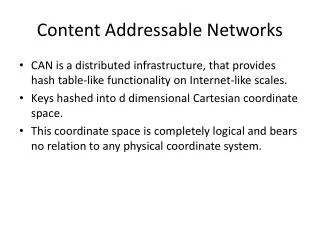
Introduction • CAN arrangement resembles a hash table. The keys are file names and the values are points in the coordinate space. • CAN is composed of many individual nodes. Each CAN node stores a chunk (called a zone) of the entire hash table. • In addition, a node holds information about a small number of “adjacent” zones in the table. • Requests (insert, lookup, or delete) for a particular key are routed by intermediate CAN nodesfrom the requests initiator towards the CAN node, whose zone contains that key. • The CAN's routing algorithm is designed to provide the following features: a. Scalabilityb. Distributivity c. Efficiency and fault-toleranced. Balanced load.
Data Model • CAN's design centers around the virtual d-dimension Cartesian coordinate space on d-torus. It is a logical coordinate space, cyclical in every dimension. • The coordinate space is dynamically partitioned among all the nodes in the system. Every node “owns” its individual zone within the overall space. • A node provides only indexing of information. • Zones in CAN can have different size, however they must have a rectangular shape.
Data Model (cont.) • Every node owns only one distinct zone. It provides direct access to the data mapped to his zone, for all users connected to this node. • In order to provide user's queries on the entire DHT(distributed hash table), a node has to forward user's queries to one of its "neighbors“. • Two nodes are neighbors if their coordinate spans overlap along d-1 dimensions and differs along one dimension. • This neighbor relationship creates a virtual grid. It allows to forward a query using some simple metrics(for example the Cartesiandistance). • A node in CAN stores a list of its neighbors, which contains neighbors‘ IP addresses and their zonecoordinates.
Data Model (cont.) This virtual coordinate space is used to store (key,value) pairs, where keys are file names and the values are IPs of computers storing the files, as follows: • To store a pair (K1,V1), key K1 is deterministically mapped onto a point P in the coordinate space using a uniform hash function. • The corresponding (key,value) pair is then stored at the node that owns the zone within which the point P lies. • To retrieve an entry corresponding to key K1, the same deterministic hash function that mapsK1 onto point P is applied. • The request is routed through the CAN infrastructure, until it reaches the node in whose zone P lies. • The set of immediate neighbors in the coordinate space serves as a routing table that enables routing between points in this space.
Routing • A CAN node maintains a coordinate routing table that holds the IP address and virtual coordinate zone of each of its immediate neighbors in the coordinate space. • A CAN message includes the destination coordinates. • Using its neighbor coordinate set, a node routes a message towards its destination by simple greedy forwarding to the neighbor with coordinates closest to the destination coordinates.
Average path length • Assume that we have a perfect situation, when every node has 2 neighbors in each dimension and node graph becomes a d-dimension grid. • The maximal path length in each dimension is because CAN uses a Cartesian space on d-torus which is cyclical. • The maximal path length for the CAN is the sum of the maximal path lengths in each dimension and it equals • The average path length is not greater than the maximal one, so it is: • These scaling results mean that for a d-dimensional space, we can grow the number of nodes (and hence zones) without increasing per node state. Then, the average path length grows as O( ).
Fault tolerance routing • If node loses all its neighbors in an optimal direction and the repair mechanism, described later, have not build the void zone, then greedy forwarding may fail. • To prevent this situation the basic routing algorithm should be extended by the following rule: • Before forwarding the request, the current node checks for its neighbors availability. The request is forwarded to the closest available node, from which greedy forwarding is resumed. • In this case the path may be non optimal, but the data is still available.
CAN construction • In this part we consider how CAN can be constructed. • We assume that there is at least one node in the system. • In this case, it is important to handle 3 different situations: 1. A new node wants to join the system. 2. A CAN node wants to leave the system. 3. A CAN node crashes or leaves the system without any notification.
Construction • The entire CAN space is divided amongst the nodes currently in the system. • To allow the CAN to grow incrementally, a new node that joins the system must be allocated its own portion of the coordinate space. • This is done by an existing node splitting its allocated zone in half, retaining half and handing the other half to the new node. • The process takes three steps (explanations about each of them appear in the next slides): 1. First the new node must find a node already in the CAN. 2. Next, using the CAN routing mechanisms, it must find a node whose zone will be split. 3. Finally, the neighbors of the split zone must be notified so that routing can include the new node.
Bootstrap • How will we get an access to the system? • Assume CAN has an associated DNS domain name which is resolved to the IP address of one of the CAN bootstrap nodes. • A bootstrap node maintains a partial list of CAN nodes which are currently in the system. • A user in this model sends a request, using CAN's domain name. His client gets an answer from one of the bootstrap nodes and automatically establishes the connection to any available CAN node.
Finding a Zone • The new node then randomly chooses a point P in the space and sends a JOIN request destined for point P. • This message is sent into the CAN via any existing CAN node. • Each CAN node then uses the CAN routing mechanism to forward the message, until it reaches the node in whose zone P lies. • This current occupant node then splits its zone in half and assigns one half to the new node. • The split is done by assuming a certain ordering of the dimensions in deciding along which dimension a zone is to be split (so that zones can be re-merged when nodes leave). • The (key, value) pairs from the half zone to be handed over are also transferred to the new node.
Joining the Routing • The previous occupant updates its neighbor set to eliminate those nodes that are no longer its neighbors. • Having obtained its zone, the new node learns the IP addresses of its coordinate neighbor set from the previous occupant. • Both the new and old nodes’ neighbors are informed of this reallocation of space. • The addition of a new node affects only a small number of existing nodes in a very small locality of the coordinate space. • The number of neighbors a node maintains depends only on the dimensionality of the coordinate space and is independent of the total number of nodes in the system, which is importantforCANs with huge numbers of nodes.
Node's departure (the node tells the system about its leaving) • In this case it is necessary to replace leaving node's zone and to support a routing under this zone. • CAN offers the following algorithm to do it: 1. The leaving node finds such a neighbor which zone can be merged with it and forms a proper zone – rectangularly shaped. 2. If such a neighbor does not exist the leaving node chooses any its neighbor. In this case a node covers two different zones in the same time. However, CAN has an inconsistent state, one node owns 2 zones, and it should be fixed by additional algorithm. 3. The leaving node's zone is replaced to the chosen neighbor. 4. Leaving node's neighbors are notified that another node is now their neighbor instead of the leaving one. 5. The node, which receives the zone, changes its neighbor list and notifies all its neighbors.
Node's crash (the node doesn’t notify the system about its leaving) • Is handled through an takeover algorithm which ensures that one of failed node's neighbors takes over the zone. • However the data, (key, value) pairs, owned by the failed node would be lost until the state is refreshed by data owners (users will connect to the CAN and share their files again). • Under normal conditions a node sends periodic update messages to each of its neighbors giving its zone coordinates and a list of its neighbors and their zone coordinates. • The prolonged absence of an update message from a neighbor signals its failure. • If some node has decided that its neighbor has failed it initiates a TAKEOVER mechanism (described in the next slide). • Note that several neighbors can start a TAKEOVER mechanism independently.
Node's crash (cont.) • TAKEOVER mechanism: 1. The node initializes a timer in proportion to its zone volume. 2. If a timer is expired it sends a TAKEOVER message to all failed node's neighbors, which contains the volume of its sender zone. 3. A neighbor which gets a TAKEOVER message compares its own zone volume to the sender zone volume and if its zone is smaller then this node sends a new TAKEOVER message as described above. 4. A failed node's neighbor which did not get a TAKEOVER message with smaller zone should take the zone of the departured node.
Node's crash (cont.) • The two main advantages of this mechanism are that: 1. It allows to assign a failed node's zone to the smallest node (balanced load). 2. It works without any centralized control. • Both the normal leaving procedure and the immediate takeover algorithm can result in a node holding more than one zone. • To prevent repeated further fragmentation of the space, a background zone-reassignment algorithm, described in the next slide, is applied.
Preventing fragmentation • A node I performs search on the partition, as follows: 1. Let dkbe the last dimension along which node I’s zone was halved (this can be simply saved in the node). 2. From its neighbors, node I selects a neighbor J that differs I along dimension dk, such that J belongs to the zone that forms the other half to I’s zone by the last split along dimension dk. 3. If the volume of J’s zone equals I’s volume, then I and J are a pair of sibling leaf nodes whose zones can be combined. 4. If J’s zone is smaller then I’s then I forwards the search request to node J, which then repeats the same steps. 5. This process repeats until a pair of sibling nodes is found.
What have we learned • Client-Server model. • Different Peer-to-Peer models: 1. Centralized model 2. Decentralized model. • General Overview of CAN: 1. Data Model of CAN. 2. Routing in CAN. 3. CAN construction. 4. Nodes Departure. 5. Nodes Crash. • During the next hour Ilya will talk about: 1. Design improvements. 2. CAN applications and citations (very shortly).