Download
1 / 80
0 likes | 12 Views
COMPUTER MAINTENANCE AND TROUBLESHOOTING

E N D
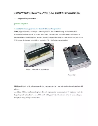
COMPUTER MAINTENANCE AND TROUBLESHOOTING 1.1 Computer Components Part 1 personal computers > Identify the names, purposes and characteristics of storage devices FDD (floppy disk drive)has only 1.4 Mb storage space. Was used for backup of data and mode of transferring data from one PC to another. As of 2005 3½-inch drives were still common equipment on many new PCs other than laptops. But have become pretty much obsolete, portable storage options, such as USB storage devices and recordable or rewritable CDs / DVDs have taken its place. Floppy Connection on Motherboard Floppy Drive HDD (hard disk drive) is a data storage device that stores data on a magnetic surface layered onto hard disk platters. As of June 2006 the smallest desktop hard disk still in production has a capacity of 40 gigabytes, while the largest-capacity internal drives are a 3/4 terabyte (750 gigabytes), with external drives at or exceeding one terabyte by using multiple internal disks. 1
Types of Hard Drives • ESDI (Enhanced Small Disk Interface) was an interface developed by Maxtor to allow faster communication between the PC and the disk. • SCSI (Small Computer System Interface) was an early competitor with ESDI, originally named SASI for Shugart Associates. • ATA / IDE and EIDE (Advanced Technology Attachment, also known as Enhanced Integrated Drive Electronics) • SATA (Serial ATA) CD / DVD / RW (e.g. drive speeds, media types) CD-ROM Compact Disc Read-Only Memory Used for data storage and data transfer. A standard 120mm CD-ROM holds 650 or 700 Mb of data. DVD-ROM Digital Versatile Disc or Digital Video Disc is an optical disc storage media format that can be used for data storage, including movies with high quality video and sound. DVDs resemble compact discs as their physical dimensions are the same but they are encoded in a different format and at a much higher density allowing for a greater data capacity of about 4.7 GB CD-RW • CD-RW recorder can rewrite 700 MB of data to a CD-RW disc roughly 1000 times. • CD-RW recorders can also write CD-R discs. Except for the ability to completely erase a disc, CD-RWs act very much like CD-Rs. • CD-RWs cannot be read in CD-ROM drives built prior to 1997. • CD-R is considered a better technology for archival purposes as disc contents cannot be modified. DVD-RW • Rewritable optical disc with equal storage capacity to a DVD-R, typically 4.7 GB. 2
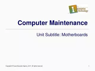
• Primary advantage of DVD-RW over DVD-R is the ability to erase and rewrite to a DVD-RW disc. • DVD-RW discs may be written to about 1,000 times before needing replacement, making them comparable with the CD-RW standard. • DVD-RW discs are commonly used for volatile data, such as backups or collections of files. Dual Layer recording allows DVD-R and DVD+R discs to store significantly more data, up to 8.5 Gigabytes per disc, compared with 4.7 Gigabytes for single-layer discs. > Removable storage Tape drives mainly for backup and long-term storage. Can be connected with SCSI (most common), parallel port, IDE, USB, FireWire or optical fibre. Tape drives can range in capacity from a few megabytes to upwards of 800 GB compressed. External CD-RW and hard drive May be used for backup, easy transfer of data to another PC, and are good choices for offsite backup data storage in case of fire et.. Thumb drive, flash and SD cards small, lightweight, removable and rewritable data storage devices. Some recent USB flash drives act as two drives - as a removable disk device , and as a USB floppy drive. This is likely intended to make it easier to use them as a bootable device. > Identify the names, purposes and characteristics of motherboards A motherboard, also known as a mainboard, logic board, or system board, and sometimes abbreviated as mobo, is the central or primary circuit board of the computer. A typical computer is built with the microprocessor, main memory, and other basic components on the motherboard. Other components of the computer such as external storage, control circuits for video display and sound, and peripheral devices are typically attached to the motherboard via ribbon cables, other cables, and power connectors. Form Factor Form factor refers to the size and format of motherboards ATX (Advanced Technology Extended) is a full size board measuring 12" wide by 9.6" deep (305 mm x 244 mm) BTX (for Balanced Technology Extended) was originally slated to be the replacement for the aging ATX motherboard, but it has not been widely accepted by the market as of early 2006. microATX is a small motherboard size of 9.6" x 9.6" (244 mm x 244 mm). Compared to full size ATX, microATX has reduced the amount of I/O slots but a smaller power supply can be used. > Components Common Motherboard Layout (INTEL Socket T (LGA775)) 3
1 CPU Socket 2 CPU_FAN - CPU cooling fan connector 3 DIMM1~2 - 240-pin DDR2 SDRAM slots 4 IRDA - Infrared header 5 FDD - Floppy diskette drive connector 6 ATX1 - Standard 24-pin ATX power connector 7 IDE1 - Primary IDE channel 8CLR_CMOS - Clear CMOS jumper 9SATA1~4 - Serial ATA connectors 10 PANEL1 - Panel connector for case switches and LEDs 11 USB1-2 - Front Panel USB headers 12 1394a - IEEE 1394a header 13 BIOS_WP - BIOS flash protect jumper 14 COM2 - Onboard Serial port hader 15 WOL1 - Wake On LAN connector 16 S/PDIF - SPDIF out header 17 F_AUDIO - Front panel audio header 18 AUX_IN - Auxiliary In connector 4
19 PCI1~2 - 32-bit add-on card slots 20 PCIE1 - PCI Express x1 slot 21 PCIEX16 - PCI Express slot for graphics interface 22 SYS_FAN - System cooling fan connector 23 ATX12V - Auxiliary 4-pin power connector > Integrated I/Os Rear panel on of a motherboard with many integrated inputs and outputs (I/O's). PS2 Mouse Used to connect a PS/2 pointing device. PS2 Keyboard Used to connect a PS/2 keyboard. Parallel Port (LPT1) Used to connect printers or other parallel communications devices. Serial Port Used to connect serial devices such as mice or (COM1) fax/modems. VGA Port Connect your monitor to the VGA port. 1394a Port Use the 1394a port to connect to any firewire device. LAN Port Used to connect an RJ-45 cable to a Network hub or router. USB Ports Used to connect USB devices such as printers, scanners cameras et... Audio Ports Used to connect audio devices. The D port is for stereo line-in signal, while the F port is for microphone in signal. This motherboard supports 8-channel audio devices that correspond to the A, B, C, and E port respectively. In addition, all of the 3 ports, B, C, and E provide users with both right & left channels individually. • • A. Center & Woofer B. Back Surround 1.1 Computer Components Part 2 1.1 Identify the fundamental principles of using personal computers part 2 > Memory slots RIMM Slots: were commonly used on the Intel Pentium 4 motherboards. Unlike most other types of computer memory, computers that support RIMM require a continuous signal. If a memory slot is left empty the PC will not 5
work. The empty slot must be filled with another RIMM module or a C-RIMM pass through module which enables a continuous signal. < Installed DIMM < Open DIMM Slots DIMM Slots: come in three common pin configurations. • • • 240-pin slots - for DDR2 SDRAM memory for desktop computers. 184-pin slots - for DDR SDRAM memory for desktop computers. 168-pin slots - commonly found in Pentium and Athlon systems. Processor sockets A motherboard is designed for a certain range of processors. One of the determining factors of processor compatibility is the slot or socket connector soldered onto the board. 242-contact and 330-contact slot connectors were used for a short time to allow for L2 cache to be packaged close to the processor die. Processor manufacturing advancements now allow L2 cache to be manufactured on the same die as the processor, requiring a smaller form-factor processor packaging. PGA (pin grid array) sockets are more common, flexible, and compact, but have many variations in the amount of pin connects and pin layouts. AMD Proccessors CPU Socket Processors PIN's AMD Athlon (650 MHz - 1400 MHz) AMD Athlon XP (1500+ - 3200+) AMD Duron (600 MHz - 1800 MHz) AMD Sempron (2000+ - 3300+) AMD Athlon MP (1000 MHz - 3000+) Socket A 453 AMD Athlon 64 (2800+ - 3700+) AMD Sempron (2500+ - ) Socket 754 754 6
AMD Turion 64 (ML and MT) AMD Athlon 64 (3000+ - 4000+) AMD Athlon 64 FX AMD Athlon 64 X2 Some AMD Opteron 1xx series Some Sempron 3xxx Socket 939 939 Socket 940 NOT compatible with Socket AM2 940 pin CPUs AMD Athlon 64 FX AMD Opteron 940 Athlon 64 Athlon 64 X2 Athlon 64 FX Opteron Sempron 940 Socket AM2 Athlon 64 Athlon 64 X2 Athlon 64 FX Sempron Socket AM3 ? INTEL Proccessors CPU Socket Processors PIN's Intel Pentium 4 (1.4 - 3.4 GHz) Intel Celeron (1.7 - 3.2 GHz) Celeron D (to 3.2 GHz) Intel Pentium 4 Extreme Edition (3.2, 3.4 GHz) Socket 478 478 Intel Pentium M (900 MHz - 2.267 GHz) Intel Celeron M (800 MHz - 1.733 GHz) Intel Core Duo (1.667 - 2.167 GHz) Intel Core Solo (1.667 GHz) VIA C7-M (1,5 GHz and 1,8 GHz) Socket 479 479 Intel Pentium 4 (2.66 - 3.80 GHz) Intel Celeron D (2.53 - 3.46 GHz ) LGA775 775 7
Intel Pentium 4 Extreme Edition (3.20 - 3.73 GHz) Intel Pentium D (2.66 - 3.60 GHz) Intel Pentium Extreme Edition (3.20 - 3.73 GHz) Intel Core 2 Duo (1.60 - 2.67 GHz) Intel Core 2 Extreme (2.66 - 2.93 GHz) Intel Core Solo Intel Core Duo Intel Dual-Core Xeon (1.67, 2.0) Intel Core 2 Duo (T5x00, T7x00) Socket M 478 External cache memory L2 Cache: Now usually found on the processor. The size of 2nd level cache. L2 Cache is ultra-fast memory that buffers information being transferred between the processor and the slower RAM in an attempt to speed these types of transfers. L3 Cache: Is a type of cache that is found on the motherboard instead of the processor. The size of 3rd level cache, typically larger then L2. L3 Cache is ultra-fast memory that buffers information being transferred between the processor and the slower RAM in an attempt to speed these types of transfers. Integrated Level 3 cache provides a faster path to large data sets stored in cache on the processor. This results in reduced average memory latency and increased throughput for larger High-end Desktop workloads. Bus architecture Front side buses serve as a backbone between the CPU and a chipset. The chipset (northbridge and a southbridge) is the connection point for all other buses in the system. The PCI, AGP, and memory buses all connect to the chipset to allow for data to flow between the connected devices. Chipsets The motherboard chipset consists of a north bridge, or Memory Controller Hub (MCH), which is responsible for controlling communication between system memory, the processor, AGP, and the south bridge, or I/O Controller Hub (ICH). The ICH controls communication between PCI devices, system management bus, ATA devices, AC'97 (audio), USB, IEEE1397 (firewire), and LPC controller. These chipsets are soldered onto the motherboard and cannot be changed or upgraded. Bus slots 8
PCI: Peripheral Component Interconnect, is a specification introduced by Intel Corporation that defines a local bus system that allows up to 10 PCI-compliant expansion cards to be installed in the computer. Many netword, modem, sound, and graphics adapters et... use the PCI bus. The PCI bus is being replaced by PCI Express AGP: Accelerated Graphics Port , used for graphics adapters. The AGP port is being replaced by the new PCIe slot. PCIe: PCI Express (PCIe) is a new I/O bus technology that, over time, will replace Peripheral Component Interconnect (PCI), PCI-X, and the Accelerated Graphics Port (AGP). PCIe hardware is backwards compatible with PCI software (not with hardware PCI slots) on the Microsoft Windows 2000 and Microsoft Windows XP operating systems. The PCI features supported by current Windows operating systems will continue to work with PCIe without any need for modifications in the applications, drivers, or operating system; however, the advanced PCIe features will be natively supported only in Windows Vista and later versions of Windows. PCIe slots today are mostly used for graphics cards which require the greater bandwidth PCIe is capable of. AMR: Audio Modem Riser, is an expansion slot found on the motherboards of some Pentium III, Pentium 4, and Athlon personal computers. Drawbacks of AMR are that it eliminates one PCI slot, it is not plug and play, and it does not allow for hardware accelerated cards (only software-based). CNR: Communications and Networking Riser, is a slot found on some motherboards. A motherboard manufacturer can choose to provide audio, networking, or modem functionality in any combination on a CNR card. Today nearly all riser technologies, such as ACR, AMR, and CNR, have been generally obsoleted in favor of on-board or embedded components. PATA: In 2003, the original ATA (Advanced Technology Attachment) was retroactively renamed Parallel ATA (PATA) IDE: Integrated Drive Electronics EIDE: Enhanced IDE, sometimes referred to as Fast ATA or Fast IDE Are standard interfaces for connecting storage devices such as hard disks and CD-ROM drives inside personal computers. 9
SATA: Serial ATA (Advanced Technology Attachment) is a computer bus technology primarily designed for transfer of data to and from hard disks and optical drives. The SATA connectors will only fit in one orientation. The main differences between the serial interconnect and the parallel interconnect of ATA are as follows: • Serial ATA is point to point, meaning only one storage device can be connected to a single Serial ATA cable. Parallel ATA has a shared channel and can connect up to two storage devices on a single cable. Serial ATA is faster. Currently Serial ATA transfers data at a rate of 150 megabytes (MB) per second and will likely advance to 300 MB and 600 MB per second in the near future. Serial ATA has a thinner cable and a smaller connection that is keyed so they cannot be connected incorrectly, unlike some parallel ATA cables. • • SCSI Technology Small Computer System Interface) is a set of standards for physically connecting and transferring data between computers and peripheral devices. SCSI interfaces that have an 8-bit data bus, referred to as narrow, allow up to seven devices (hard drives, tape drives, CD-ROM drives, removable drives/disks and scanners) connected to one SCSI adapter/controller. It would be eight devices if you count the controller card. SCSI interfaces with 16-bit data bus, referred to as wide, interfaces allow up to 15 devices (16 devices including the controller card). Types of SCSI interfaces: • SCSI-1: Uses an 8-bit bus, supports data transfer speeds of 4 MBps. • SCSI-2: Uses a 50-pin connector instead of a 25-pin connector, and supports multiple devices. It is currently the most common type of SCSI. Data transfer speeds are typically around 5 MBps. • Wide SCSI: Uses a wider cable (168 cable lines to 68 pins) to support 16-bit data transfers. • Fast SCSI: Uses an 8-bit bus, but doubles the clock rate to support data transfer speeds of 10 MBps. • Fast Wide SCSI: Uses a 16-bit bus and supports data transfer speeds of 20 MBps. • Ultra SCSI: Uses an 8-bit bus, supports data rates of 20 MBps. • SCSI-3: Uses a 16-bit bus, supports data rates of 40 MBps. Also called Ultra Wide SCSI. • Ultra2 SCSI: Uses an 8-bit bus, supports data transfer speeds of 40 MBps. • Wide Ultra2 SCSI: Uses a 16-bit bus, supports data transfer speeds of 80 MBps. 10
SCSI Termination The two SCSI devices at either end of the chain must be terminated; the other devices should not be terminated. If only an internal cable is used, the adapter card and the device at the end of the cable need to be terminated, but the other devices in between should not be terminated. If using an internal cable and an external cable, the two devices located at the end of each cable should be terminated. To terminate or not terminate a device, the terminators are inserted/removed or enabled/disabled with jumpers or DIP switches. Some SCSI devices can be automatically terminated. To terminate/not terminate a device, you would either insert or remove the terminators on the end device or enabled/disabled them with jumpers or DIP switches. Some SCSI devices have automatic termination. Today, most have a jumper to enable or disable the termination. Internal daisy chain (image from intel.com) External daisy chain (image from intel.com) 11
Internal External daisy chain (image from intel.com) There are several different kinds of termination used on SCSI buses. They differ in the electrical circuitry that is used to terminate the bus. Better forms of termination make for more reliable SCSI chains; the better the termination, the fewer problems (all else being equal) with the bus, though cost is generally higher as well. In general terms, slower buses are less particular about the kind of termination used, while faster ones have more demanding requirements. In addition, buses using differential signaling (either HVD or LVD) require special termination. • Passive terminator– The passive terminator uses special electrical resistors to act as voltage dividers. Since they help ensure that the chain has the correct impedance load, they prevent signals from reflecting or echoing when the signal reaches the end of the chain. Passive terminating resistors work well for chains of short distances (2-3 feet) and slower speeds (SCSI-1 specification). The chain should never exceed 6 meters. It is for single-ended SCSI buses only that should only be used in narrow (8-bit) SCSI busses running at 5 MHz. • Active Termination– Active termination acts as voltage regulator to maintain a stable voltage through the chain by utilizing the termination power lines to compensate for voltage drops. Since the active termination helps reduce noise, it allows for longer cable lengths and faster speeds. In fact, active termination is the minimum required for any of the faster-speed single-ended SCSI buses. The chain should never exceed 18 meters. It is for single-ended SCSI buses only. • Forced Perfect Terminator (FPT) – The Forced Perfect Terminator diode clamps are added to the circuitry to automatically match the line impedance by forcing the termination to the correct voltage thus allowing “perfect” termination. It is for single-ended SCSI buses only and should be used for single-ended applications that experience high levels of electrical noise. • High Voltage Differential (HVD) – Buses using high voltage differential signaling require the use of special HVD terminators. 12
• Low Voltage Differential (LVD) – Newer buses using low voltage differential signaling also require their own special type of terminators. In addition, there are special LVD/SE terminators designed for use with multimode LVD devices that can function in either LVD or SE modes; when the bus is running single-ended these behave like active terminators. Note: Many internal cables have a built-in LVD terminator at the end of the cable. > BIOS / CMOS / Firmware Basic input/output system (BIOS) is the set of essential software routines that test hardware at startup, start the operating system, and support the transfer of data among hardware devices. The BIOS is stored in read-only memory (ROM) so that it can be executed when you turn on the computer. Although critical to performance, the BIOS is usually invisible to computer users. The BIOS Setup Utility displays the PC system’s configuration status and provides you with options to set system parameters. The parameters are stored in battery-backed-up CMOS RAM that saves this information when the power is turned off. When the system is turned back on, the system is configured with the values you stored in CMOS. Most BIOS Setup Utilities enable you to configure: • Hard drives, diskette drives and peripherals • Video display type and display options • Password protection from unauthorized use • Power Management feature (CMOS) complementary metal oxide semiconductor is an on-board semiconductor chip powered by a CMOS battery inside IBM compatible computers that stores information such as the system time and system settings for your computer. Firmware is software that is embedded in a hardware device. It is often provided on flash ROMs or as a binary image file that can be uploaded onto existing hardware by a user. Most devices attached to modern systems are special- purpose computers in their own right, running their own software. Some of these devices store that software ("firmware") in a ROM within the device itself. Over the years, however, manufacturers have found that loading the firmware from the host system is both cheaper and more flexible. As a result, much current hardware is unable to function in any useful way until the host computer has fed it the requisite firmware. This firmware load is handled by the device driver. Riser card / daughter board Riser card is a PC expansion card that can be added to a PC to give it audio, modem or networking capabilities. Daughter boards are expansion boards that commonly connect directly to the motherboard and give the computer an added feature such as modem, audio capability ect.. . Today, these types of boards are not found or used in desktop computers and have been replaced with PCI boards. But, many laptops still use these types of boards. 13
1.1 Computer Components Part 3 Posted March 14th, 2007 by admin 1.1 Identify the fundamental principles of using personal computers part 3 > Identify the names, purposes and characteristics of power supplies: Power Connections on typical modern motherboard ATX Today, PCs will use either an ATX or ATX12V power supply. It contains software control of the power on/off signal so that it can shut down the system. Since the ATX/ATX12V power supplies are software activated/deactivated, you need to connect the “Power SW” cable from the chassis to the motherboard. Most power supplies require to have a load connected to the power supply. In other words, you must have at least one component such as a drive or motherboard connected to the power supply. Most power supplies designed to be used in the United States operate at 120 volts with a frequency of 60 Hz. In other nations, the supply voltage and frequency may be different. In Europe, you will find 230 volt with a 50 Hz frequency as the standard. Today, most PC power supplies will operate at either voltage. Some can automatically switch over to the proper voltage while most are done by using a small switch on the rear of the power supply. Ensure when plugging in your PC and turning it on, the correct voltage is selected. If you have a power supply switched over to 230 V and the 14
voltage is 120 V, the PC will not boot up. Unfortunately, if the power supply is set to 120 V and it is connected to a 230 V outlet, it will seriously damage your power supply and other important components. The ATX12V power supply provides increased 12 V, 3.3 V, and 5 V current and provides additional cooling capability. An ATX12V power supply can be easily identified by the addition of an additional new 2x2 pin connector and an optional 1X6 pin connector. ATX Pin Outs The ATX power supply uses the PS_ON signal to power up the system. A +5 volt signal is constantly sent through pin 14 (PS_ON) of the ATX power connector. When the PS_ON is shorted tells the power supply to turn on and start the boot process. A push button contact switch is connected to two pins on the motherboard that link to the PS_ON signal to ground. When the push button is pushed, it connects the PS_ON signal to ground. When the push button is pushed, it connects the PS_ON signal with ground, shorting it out. Therefore, when you are installing an ATX motherboard, you need to connect the push button wires (usually labeled PWR SW) to the motherboard. If you decide to test a motherboard without physically installing it into an ATX case, you can start the system by either connecting a push button switch to the motherboard and pressing the button or by taking a small screw driver and make contact with the two pins that make up the power switch connector. Since the switch only toggles the on/off status, the switch carries only +5 V of DC power, rather than the full 110 V AC current used in the T power supplies. Besides supplying the power to the PC components, the power supply also provides the power-good signal. During boot up, the processor tells the computer to constantly reset. As soon as the power supply performs a self-test, testing if all voltage and current levels are acceptable, the power supply will send a power good signal (+5 volts) to the microprocessor. When the power good signal is sent, the computer will finish the boot process. 15
ATX Power Supply 24 pin connection on mainboard, some newer motherboards with 24 pin connections can accept both 20 and 24 pin connectors 20 and 24 pin main power connectors 20 main and 4 pin secondary connector - AMD Athlon 64 and Intel Pentium 4 processors require a power supply with an extra 12V connector that is connected to a 4-pin header on the motherboard 16
8 Pin cpu connector - On some motherboards, for example boards that support Intel dual-core processors have a secondary 8 pin connection. The ATX form factor has five main power supply designs: ATX - 20 pin connector (Used through Pentium III and early Athlon XP) WTX - 24 pin connector (Pentium II and III, Xeon and Athlon MP) AMD GES - 24 pin main connector, 8 pin secondary connector (some dual-processor Athlon) ATX12V - 20 pin main connector, 4 pin secondary connector, 8 pin tertiary connector (Pentium 4 and mid/late Athlon XP & Athlon 64) EPS12V - 24 pin main connector, 8 pin secondary connector, optional 4 pin tertiary connector (Xeon and Opteron) defined in SSI specification ATX12V 2.0 - 24 pin main connector, 4 pin secondary connector (Pentium 4, Core 2 Duo, and Athlon 64 with PCI Express) ATX12V 2.2 - One 20/24-pin connector, one ATX12V 4 pin connector. Many power supply manufacturers include a 4 plus 4 pin, or 8 to 4 pin secondary connector instead, which can also be used as the secondary EPS12V connector. CPU Power Supply ATX plug P4 connector (4-pin 12V) 20-pin, sometimes 24- pin AMD Socket 754 ATX12V 1.3 or higher sometimes needed 20-pin, sometimes 24- pin AMD Socket 939 ATX12V 1.3 or higher sometimes needed Intel Socket 423 ATX12V 1.3 or higher 20-pin needed Intel Socket 478 ATX12V 1.3 or higher 20-pin needed 24-pin, sometimes 20- pin Intel Socket 775 ATX12V 2.01 or higher needed > Identify the names purposes and characteristics of processor / CPUs CPU chips: Central Processing Unit is the component on the motherboard that interprets instructions and processes data contained in computer programs. The CPU combines the control unit, storage unit, and arithmetic unit. • Control unit interprets the instructions given to the computer. • Internal storage is where the program of instructions is kept and where data from the input devices are sent. • External storage can consist of disk and tapes. 17
• Arithmetic unit actually does the calculation required by the program. CPU technologies: Hyperthreading is Intel's trademark for their implementation of the simultaneous multithreading technology on the Pentium 4 microarchitecture. The technology improves processor performance under certain workloads. Dual core a CPU that includes two complete execution cores per physical processor. It has combined two processors and their caches and cache controllers onto a single integrated chip. Dual-core processors are well-suited for multitasking environments because there are two complete execution cores instead of one, each with an independent interface to the frontside bus. Since each core has its own cache, the operating system has sufficient resources to handle most compute intensive tasks in parallel. Throttling is sort of enforced power management: Even when the system is highly active, the CPU is "put to sleep" for short amounts of time. This is done when the temperature is critically high, or, by request of the user, when the system shall use less power to allow longer system usage when on battery power. Micro code (MMX) technology is designed to accelerate multimedia and communications applications by including new instructions and data types that allow applications to achieve better performance. Overclocking is the process of forcing a computer component to run at a higher clock rate than it was designed for or was designated by the manufacturer. Cache memory is used by the central processing unit of a computer to reduce the average time to access memory. The cache is a smaller, faster memory which stores copies of the data from the most frequently used main memory locations. As long as most memory accesses are to cached memory locations, the average latency of memory accesses will be closer to the cache latency than to the latency of main memory. Voltage Regulator Module (VRM) is an electronic device that provides a microprocessor the appropriate supply voltage. It can be soldered to the motherboard or be an installable device. It allows processors with different supply voltage to be mounted on the same motherboard. Some voltage regulators provide a fixed supply voltage to the processor, but most of them sense the required supply voltage from the processor. In particular, VRMs that are soldered to the motherboard are supposed to do the sensing, according to the Intel specification. Speed (real vs. actual) Between 2001 and 2003, Intel and AMD made few changes to the designs of their processors. Most performance increases were created by raising the processor's clock speed rather than improving the microprocessor's core. Around mid 2004, Intel encountered serious problems in increasing their Pentium 4's clock speed beyond 3.4 GHz because of the enormous amount of heat generated by the already hot Prescott core processor 18
when working at higher clock speeds. In response, Intel started exploring ways to improve the performance of its microprocessors in ways other than raising the clock speeds of the processors such as increasing the sizes of the processors' caches and using multiple processing cores in its processors. Because of the philosophy change, a Pentium 4 clocked at 3.0 GHz with a 1MB L2 cache could now outperform a 3.4 GHz Pentium 4 with 512KB L2 Cache. Clock speeds could no longer solely differentiate the performance of different Pentium 4s. As a result, Intel has adopted a PR rating of its own using three digit numbers. Intel now faces the challenge of making consumers compare its processors based on PR ratings rather than raw clock speed, ironically a problem which Intel created itself. Some analysts regard the PR scheme (and a raw MHz/ GHz rating) as nothing more than a marketing tactic, rather than as a useful measure of CPU performance. Many professionals or interested amateurs now consult extensive benchmark tests to determine system performance on various applications. 32 vs. 64 bit A change from a 32-bit to a 64-bit architecture is a fundamental alteration, as most operating systems must be extensively modified to take advantage of the new architecture. Other software must also be ported to use the new capabilities; older software is usually supported through either a hardware compatibility mode (in which the new processors support the older 32-bit version of the instruction set as well as the 64-bit version), through software emulation, or by the actual implementation of a 32-bit processor core within the 64-bit processor die (as with the Itanium processors from Intel, which include an x86 processor core to run 32-bit x86 applications). The operating systems for those 64-bit architectures generally support both 32-bit and 64-bit applications. > Identify the names, purposes and characteristics of memory Types of memory: Common DRAM PIN Count: • DIMM 168-pin (SDRAM) • DIMM 184-pin (DDR SDRAM) • DIMM 240-pin (DDR2 SDRAM) DRAM: Dynamic Random Access Memory, stores data as electronic signals. These signals must be constantly refreshed to keep them from dissipating. SRAM: Synchronous Random Access Memory. SDRAM: Synchronous Dynamic Random-Access Memory. A DRAM technology that uses a clock to synchronize signal input and output on a memory chip. The clock is coordinated with the CPU clock so the timing of the memory chips and the timing of the CPU are "in synch." The synchronization eliminates time delays and allows for fast consecutive read and write capability, thereby increasing the overall performance of the computer. SDRAM has two separate memory banks that operate simultaneously, while one bank prepares for access, the other is being accessed. SDRAM is controlled by the system clock. SDRAM can only be used in computers designed for it and cannot be mixed with any other type of memory. SDRAM can operate at 100MHz, 133Mhz and features a burst mode that allows it to address blocks of information instead of small data bits. 19
DDR / DDR2 DDR (DOUBLE DATA RATE) finds its foundations on the same design core of SDRAM, yet adds advances to enhance its speed capabilities. As a result, DDR allows data to be sent on both the rising and falling edges of clock cycles in a data burst, delivering twice the bandwidth of standard SDRAMS. DDR essentially doubles the memory speed from SDRAMs without increasing the clock frequency. DDR memory modules have 184 pins and one notch near the center, while DDR2 have 240 pins. The key difference between DDR and DDR2 is that in DDR2 the bus is clocked at twice the speed of the memory cells, allowing transfers from two different cells to occur in the same memory cell cycle. Thus, without speeding up the memory cells themselves, DDR2 can effectively operate at twice the bus speed of DDR. DDR2 DIMMs are not backwards compatible with DDR DIMMs. The notch on DDR2 DIMMs is in a different position than DDR DIMMs, and the pin density is slightly higher than DDR DIMMs. DDR2 is a 240-pin module, DDR is a 184-pin module. • 184-pin DIMM: DDR 200/266/333/400 DDR SDRAM • 240-pin DIMM: DDR2 400/533/667/800 DDR-2 SDRAM DOUBLE DATA RATE 3 SYNCHRONOUS DRAM (DDR3 SDRAM) DDR3 is the third generation of Double Data Rate (DDR) SDRAM memory. Similar to DDR2, it is a continuing evolution of DDR memory technology that delivers higher speeds (up to 1600 MHz), lower power consumption and heat dissipation. It is an ideal memory solution for bandwidth hungry systems equipped with dual and quad core processors and the lower power consumption is a perfect match for both server and mobile platforms. DDR3 modules will be available in the second half of 2007. RAMBUS: Direct Rambus DRAM or DRDRAM (sometimes just called Rambus DRAM or RDRAM) is a type of synchronous dynamic RAM, designed by the Rambus Corporation. Not widely in PC's today. Operational characteristics: Parity versus non-parity Parity is a quality control method that checks the integrity of data stored in a computer's memory. Parity works by adding an extra bit of data to each byte to make the total number of 1's either odd or even. An error is detected if the parity circuit determines that this number has changed, indicating that some of the data may have been lost or otherwise corrupted. Two different parity protocols exist, even parity and odd parity. Parity protocols are capable of detecting 20
single bit errors only. To enable multiple-bit error detection, manufacturers must use a more advanced form of error checking called Error Correcting Code (ECC). ECC vs. non-ECC Error Correction Code. A method used to check the integrity of data stored in memory . ECC memory improves data integrity by detecting errors in memory and is more advanced than parity because it can detect both multiple-bit errors and single-bit errors (parity only detects single-bit errors). ECC is typically found in high-end PCs and file servers where data integrity is key. • Most computers designed for use as high-end servers support ECC memory. • Most computers designed for use at home or for small businesses do not use ECC memory. Single-sided vs. double-sided A physical terms meaning that the memory chips are arranged on one or both sides of the memory module 1.1 Computer Components Part 4 1.1 Identify the fundamental principles of using personal computers part 4 > Identify the names, purposes and characteristics of display devices, for example: Projectors A video projector takes a video signal and projects the corresponding image on a projection screen using a lens system. All video projectors use a very bright light to project the image, and most modern ones can correct any curves, blurriness, and other inconsistencies through manual settings. Video projectors are widely used for conference room presentations, classroom training, and home theatre applications. Common display resolutions for a portable projector include SVGA (800×600 pixels), XGA (1024×768 pixels), and 720p (1280×720 pixels). A Projector can be connected to a PC in many ways ie: HDMI, Component Video,VGA, DVI, Composite Video (RCA), S-Video, RS-232 CRT 21
The CRT or cathode ray tube, is the picture tube of a monitor. The back of the tube has a negatively charged cathode. The electron gun shoots electrons down the tube and onto a charged screen. The screen is coated with a pattern of dots that glow when struck by the electron stream. Each cluster of three dots, one of each color, is one pixel. The image on the monitor screen is usually made up from at least tens of thousands of such tiny dots glowing on command from the computer. The closer together the pixels are, the sharper the image on screen. The distance between pixels on a computer monitor screen is called its dot pitch and is measured in millimeters. Most monitors have a dot pitch of .28 mm or less. A modern CRT display has considerable flexibility: it can usually handle a range of resolutions from 320 by 200 up to 2560 by 2048 pixels. LCD A liquid crystal display (commonly abbreviated LCD) is a thin, flat display device made up of any number of color or monochrome pixels arrayed in front of a light source or reflector. • Resolution: unlike CRT monitors, LCD monitors have a native-supported resolution for best display effect. • Dot pitch: the granularity of LCD pixels. The smaller, the better. • Viewable size: The length of diagonal of a LCD panel • Input ports: (e.g. DVI, VGA, or even S-Video ). Video Connector types: Video Card Outputs, from left to right. VGA, S-Video and DVI 22
VGA The common 15-pin VGA connector found on most video cards, computer monitors, and other devices, is almost always used solely to carry analog component video signals. Used mostly for CRT monitors but many LCD monitors also use these connectors. The common 15-pin VGA connector found on most video cards, computer monitors, and other devices, is almost universally called "HD-15". HD stands for "high-density". VGA connectors are almost always used solely to carry analog signals. Mini VGA A Mini-VGA connector is used on laptops and other systems in place of the standard VGA connector. Apart from its compact form, mini-VGA ports have the added ability to output both composite and S-Video in addition to VGA signals. DVI Digital Visual Interface (DVI) is a video interface standard designed to maximize the visual quality of digital display devices such as flat panel LCD computer displays and digital projectors. As well as digital signals, the DVI connector also includes pins providing the same analog signals found on a VGA connector, allowing a VGA monitor to be connected with a simple plug adapter. This feature was 23
included in order to make DVI universal, as it allows either type of monitor (analog or digital) to be operated from the same connector. The connector also includes provision for a second data link for high resolution displays, though many devices do not implement this. In those that do, the connector is sometimes referred to as DVI-DL (dual link). The DVI connector on a device is therefore given one of three names, depending on which signals it implements: DVI-D (digital only) DVI-A (analog only) DVI-I (digital & analog) HDMi High-Definition Multimedia Interface (HDMI) is an all-digital audio/video interface capable of transmitting uncompressed streams. HDMI is compatible with High-bandwidth Digital Content Protection (HDCP) Digital Rights Management technology. HDMI provides an interface between any compatible digital audio/video source, such as a set-top box, a DVD player, a PC, a video game system, or an AV receiver and a compatible digital audio and/or video monitor. The standard Type A HDMI connector has 19 pins, and is backward-compatible with the single-link Digital Visual Interface carrying digital video (DVI-D or DVI-I, but not DVI-A) used on modern computer monitors and graphics cards. This means that a DVI-D source can drive an HDMI monitor, or vice versa, by means of a suitable adapter or cable, but the audio and remote control features of HDMI will not be available. Because most DVI PC style displays do not have support for High-bandwidth Digital Content Protection (HDCP) on the display, the signal source may prevent the end user from viewing or especially copying certain restricted content. S-Video 24
Separate video, (S-Video) is an analog video signal that carries the video data as two separate signals (brightness and color), unlike composite video which carries the entire set of signals in one signal line. S- Video, as most commonly implemented, carries high-bandwidth 480i or 576i resolution video, i.e. standard definition video. It does not carry audio on the same cable. S-Video is mostly used to output a PC's video signal to a Television. Component / RGB Composite video is the format of an analog television (picture only) signal. Is used to output a PC's video signal to a Television. Settings: Refresh rate The refresh rate is how many times per second the screen is refreshed (redrawn). The faster the refresh rate, the less the monitor will flicker. On smaller CRT monitors (14") few people notice any change above 60–72 Hz. On larger CRT monitors (17", 19") most people would experience mild discomfort unless the refresh is set to a more comfortable 85 Hz or higher. 100 Hz is comfortable for most people. LCD monitors do not suffer from the same problems as CRT monitors because the refresh rate does not mean the same. LCD monitors will provide excellent quality and resolution at 60–Hz. The more important issue for a LCD monitor is its Response Time, Image Brightness and Image Contrast Ratio. Different operating systems set the default refresh rate differently. Windows 95 and Windows 98(SE) set the highest possible refresh rate. Windows NT based OS's such as Windows 2000 and its descendant Windows XP, however, by default set the refresh rate to the lowest supported, usually 60 Hz. 25
Old monitors could be damaged if a user set the video card to a higher refresh rate than supported by the monitor. Nowadays most monitors would simply display a notice that the video signal uses an unsupported refresh rate. To change the refresh frequency for your monitor 1. Open Display in Control Panel. 2. On the Settings tab, click Advanced. 3. On the Monitor tab, in the Refresh Frequency list, click a new refresh rate. Resolution The resolution of a monitor indicates how densely packed the pixels are. In general, the more pixels (often expressed in dots per inch), the sharper the image. Most modern monitors can display 1024 by 768 pixels, the SVGA standard. Some high-end models can display 1280 by 1024, or even 1600 by 1200. To change your screen resolution 1. Open Display in Control Panel. 2. On the Settings tab, under Screen resolution, drag the slider, and then click Apply. 3. When prompted to apply the settings, click OK. Your screen will turn black for a moment. 4. Once your screen resolution changes, you have 15 seconds to confirm the change. Click Yes to confirm the change; click No or do nothing to revert to your previous setting. 1.1 Computer Components Part 5 Posted March 24th, 2007 by admin 1.1 Identify the fundamental principles of using personal computers part 5 > Identify the names, purposes and characteristics of adapter cards Video including: PCI A specification introduced by Intel that defines a local bus system that allows up to 10 PCI-compliant expansion cards to be installed in the computer. PCI video cards were replaced by the newer AGP (Accelerated Graphics Port) Specifications: • 33.33 MHz clock with synchronous transfers • peak transfer rate of 133 MB per second for 32-bit bus width (33.33 MHz × 32 bits × (1 byte ÷ 8 bits) = 133 MB/s) • 32-bit or 64-bit bus width • 32-bit address space (4 gigabytes) 26
• 256-byte configuration space • 5-volt signaling PCIe PCI Express is a computer system bus that allows expansion cards with various capabilities to be added to a system. It is a flexible system intended to replace PCI, and AGP. While PCI Express has the same software interface as PCI and can be bridged to PCI, the cards are physically and electrically incompatible. PCIe 1.1 transfers data at 250 MB/s in each direction per lane. With a maximum of 32 lanes, PCIe allows for a total combined transfer rate of 8 GB/s in each direction. To put these figures into perspective, a single lane has nearly twice the data rate of normal PCI, AGP The Accelerated Graphics Port (also called Advanced Graphics Port, often shortened to AGP) is a high-speed point-to- point channel for attaching a graphics card to a computer's motherboard, primarily to assist in the acceleration of 3D computer graphics. Some motherboards have been built with multiple independent AGP slots. AGP is currently being phased out in favor of PCI Express. Multimedia: I / O: SCSI SCSI (Small Computer System Interface) is a set of standards for physically connecting and transferring data between computers and peripheral devices. The SCSI standards define commands, protocols, and electrical and optical interfaces. SCSI is most commonly used for hard disks and tape drives, but it can connect a wide range of other devices, including scanners, printers, and optical drives (CD, DVD, etc.). The SCSI standards promote device independence, which means that, at least in theory, almost any type of hardware can be connected via SCSI. Serial Port a serial port is a serial communication physical interface through which information transfers in or out one bit at a time. Data transfered through serial ports connected the computer to devices such as terminals or modems. Mice, keyboards, and other peripheral devices. While such interfaces as Ethernet, FireWire, and USB all send data as a serial stream, the term "serial port" usually identifies hardware more or less compliant to the RS-232 standard, intended to interface with a modem or with a similar communication device. As of 2007, the USB interface has replaced the serial port, most new computers are connected to devices through a USB connection, and often don't even have a serial port connection. USB see below Parallel A parallel port is a type of socket found on personal computers for interfacing with various peripherals. It is also known as a printer port. 27
Like the serial port, the USB interface has replaced the parallel port. As of 2006, most modern printers are connected through a USB connection. Communications including: Network Interface Adapters A hardware device that provides a computer with access to a LAN. Network interface adapters can be integrated into a computer's motherboard or take the form of an expansion card, in which case they are called network interface cards or NICs. The adapter, along with its driver, implements the data-link layer protocol on the computer. The adapter has one or more connectors for network cables, or some other interface to the network medium. The network interface adapter and its driver are responsible for functions such as the encapsulation of network layer protocol data into data-link layer protocol frames, the encoding and decoding of data into the signals used by the network medium, and the implementation of the protocol's media access control (MAC) mechanism. Modem Short for modulator/demodulator, a hardware device that converts the digital signals generated by computers into analog signals suitable for transmission over a telephone line, and back again. A dial-up connection between two computers requires a modem at each end, both of which support the same communication protocols. Modems take the form of internal devices that plug into one of a computer's expansion slots, or external devices that connect to one of the computer's serial ports. The term modem is also used incorrectly, in many cases, to describe any device that provides a connection to a wide area communications service, such as a cable or DSL connection. These devices are not actually modems, because the service is digital, and no analog/digital conversion takes place. > Identify the names, purposes and characteristics of ports and cables for example: USB (Universal Serial Bus) Universal Serial Bus, or USB, is a computer standard designed to eliminate the guesswork in connecting peripherals to a PC. It is expected to replace serial and parallel ports. A single USB port can be used to connect up to 127 peripheral devices, such as mice, modems, keyboards, digital camera's, printers, scanners, MP3 players and many more. USB also supports Plug-and-Play installation and hot plugging. • USB 1.1 standard supports data transfer rates of 12 Mbps. • USB 2.0 (Also referred to as Hi-Speed USB) specification defines a new High-speed transfer rate of 480 Mb/sec. USB 2.0 is fully compatible with USB 1.1 and uses the same cables and connectors. USB has with two connector types. The first is Type A (on the right), This connector connects to the PC's USB port. The Type B (on the left) connector and is for connecting to the relevant peripheral. 28
Where as the type A connector is truly standard, the Type B connector could be changed in size etc. with individual peripherals meaning they require there own unique cables. IEEE 1394 (FireWire) Is a personal computer (and digital audio/video) serial bus interface standard, offering high-speed communications and isochronous real-time data services. FireWire can be considered a successor technology to the obsolescent SCSI Parallel Interface. Up to 63 devices can be daisy-chained to one FireWire port. IEEE 1394 connectors are used to connect FireWire devices such as host controllers, adapters, hard drives, hubs, repeaters, and card readers. FireWire, a registered trademark of Apple Computer, is a communications protocol for the transmission of data, video, and audio over a single cable at very high bit rates. IEEE 1394 is an interface standard adopted by the Institute of Electrical and Electronics Engineers (IEEE) for digital data transfers at 400 Mbps. The popularity of IEEE 1394 is due in part to its use of a bus- powered architecture that does not require peripherals to supply their own power. Products that support the IEEE 1394 standard adhere to its specifications, but often use proprietary trade names. For example, Sony uses the term iLink to describe its FireWire products. iLink is a registered trademark of the Sony Corporation. There are two basic types of IEEE 1394 connectors: four-pin and six-pin. Four-pin or four-position FireWire connectors are used with digital video camcorders and other devices that have a small footprint and do not require external power. By contrast, six-pin or six-position connectors are used with personal computers (PCs), rewritable compact disc rewritable drives (CDRWs), external hard drives, digital audio stations, and other larger, more durable FireWire devices that use external power. Four-pin connectors are rectangular, 1/4” by 1/8” devices in which one of the longer sides is indented. Six-pin connectors are 29
rectangular, 1/2” by 3/16” devices in which one of the smaller sides is rounded. Four-pin and six-pin IEEE 1394 connectors are either straight or right-angled. RJ-11 (Registered Jack) Standard telephone cable connectors, RJ-11 has 4 wires (and RJ-12 has 6 wires). Pinout of the 1-Wire plug that connects to the socket on a TINI E20 Revision C board, or a 9097U adapter. RJ-11 Pin Signal Name 1 VCC (5 volts regulated) 2 Power Ground 3 One Wire Data 4 One Wire Ground 5 No Connect 6 V+ (unregulated DC) RJ-45 30
RJ-45 The "RJ" stands for Registered Jack. These connectors are used with 10-100BaseT cables, and resemble telephone RJ-11 connectors, but are larger. They are connected to the cable by crimping. Used for Ethernet cable connectors, where usually 8 pins (4 pairs) are used, e.g., a male-to-male cable to connect a cable or ADSL modem to the computer Ethernet network card. Applications include other networking services such as ISDN and T1. 25 Pair Color Code Chart RJ-45 Wiring (EIA/TIA-568B) Pair Wire Color Pins 2 1 white/orange 2 2 orange 3 1 white/green 1 2 blue 1 1 white/blue 3 2 green 4 1 white/brown 4 2 brown > Identify the names, purposes and characteristics of cooling systems for example heat sinks, CPU and case fans, liquid cooling systems, thermal compound In earlier PC's it was possible to cool most components using convection (passive cooling), more efficient cooling has become a necessity on many components. To cool these components, fans are used to move heated air away from the components and draw cooler air over them. Fans attached to components are usually used in combination with a heatsink to increase the surface area available for heat conduction, thereby improving the efficiency of cooling. 31
CPU topped by heatsink and fan Areas where cooling fans may be used: • Power Supply (PSU) fans : often play a double role, not only keeping the PSU itself from overheating, but also removing warm air from inside the case. • CPU fan: Used to cool the CPU (central processing unit). • Case fans: move air through the case, usually drawing cooler outside air in through the front and over the internal motherboard components expelling it through the rear. • Chipset fan: Used to cool the northbridge of a motherboard's chipset. • Graphics card fan: Used to cool the GPU and/or memory on graphics cards. • PCI slot fan: A fan mounted in one of the PCI slots, usually to supply additional cooling to the PCI and/or graphics cards. • Hard disk fan: A fan mounted next to or on a hard disk drive. 32
1.2 Computer Components Part 6 Posted March 24th, 2007 by admin 1.2 Install, configure, optimize and upgrade personal computer components > Add, remove and configure internal and external storage devices Install Hard Drive The following procedure is for a Western Digital EIDE hard drive, but is pretty much the same for all EIDE drives. The only difference being the jumper setting. Determine Appropriate Drive Configuration The default jumper setting for most new hard drives is Cable Select (CSEL). However, not all computer systems and motherboards support this setting. You will first need to determine whether your system or motherboard supports Cable Select as follows: 1. If your system does not support Cable Select or if you are uncertain, we recommend using the Master/Slave configuration. 2. If there is an existing IDE device installed, check the jumper settings to see if it is configured for Cable Select. If it is, then your system supports Cable Select. 3. If the IDE device installed is not configured for Cable Select or if you do not have an IDE device installed in your computer, check your system documentation or contact your computer/motherboard manufacturer to determine if Cable Select is supported. Set the Jumpers Jumper settings are used to determine the order in which IDE devices (i.e. hard drives, CD-ROM drive, etc.), attached to a single cable, are detected by the system. Western Digital EIDE hard drives have a 10-pin jumper block located next to the 40-pin IDE connector on the hard drive. After you have determined the appropriate drive configuration, you must jumper the drive(s) accordingly. Identify the procedure that corresponds to your configuration. Western Digital Jumper Setting 33
Connect the IDE Interface Cable to the hard drive(s): If installing the hard drive as the only drive on the cable: • Connect the black connector of the IDE interface cable to the drive. If installing two drives on the same IDE interface cable: • Jumper the bootable drive as Master and the other drive as Slave; then connect the Master drive to the black connector of the IDE interface cable and the Slave drive to the gray connector. Connect the IDE Interface Cable to the Motherboard: Attach the blue end of the IDE interface cable to the 40-pin connector on the motherboard. Match pin 1 on the IDE interface cable to the connector on the motherboard. note: The 40-pin 80-conductor cable is orientation specific. The cable connectors are color-coded: blue for the host connector, black and gray for the primary and secondary disk drives. The blue connector should be installed into the Primary IDE connector. Primary IDE Connection All Ultra ATA/66 devices should be attached to a single channel and devices that do not support Ultra ATA/66 should be connected to a separate channel. In single drive configurations, connect the primary drive to the end connector on the 40-pin 80-conductor cable. Connect the Power Supply Cable: Attach the computer system power supply cable to the 4-pin power connector on the back of your new Western Digital hard drive. The 4-pin connector is keyed to ensure proper insertion. 36
Secure the hard drive: Most drives will function normally whether they are mounted sideways or upside down (any X, Y, Z orientation). Of course, the physical design of your system may limit the positions in which the drive can be mounted. However, in all cases, you should mount the drive with all four screws for good grounding. Also ensure that there is enough air space around the drive for adequate air flow, and avoid mounting the drive near sources of excessive heat (such as some CPUs). Configure the BIOS: Run the system setup program. (usually by hitting the delete key before windows boots.) • Enable LBA mode and UDMA mode, if applicable. • Select the auto-detect option. • Save and exit the system setup program. > Drive preparation of internal storage devices including format / file systems and imaging technology How to partition and format your hard disk by using the Windows Setup program 1. Insert the Windows CD-ROM into your CD-ROM drive or DVD-ROM drive, or insert the first Windows Setup disk into the floppy disk drive, and then restart the computer. 2. If you are starting the computer from the Windows CD-ROM, select any options that are required to start the computer from the CD-ROM drive if you are prompted to do this. 37
Note: If your hard disk controller requires a third-party original equipment manufacturer (OEM) driver, press F6 to specify the driver. 3. At the Welcome to Setup page, press ENTER. 4. Press F8 to accept the Windows Licensing Agreement. 5. If an existing Windows installation is detected, you are prompted to repair it. To bypass the repair, press ESC. 6. All the existing partitions and the unpartitioned spaces are listed for each physical hard disk. Use the ARROW keys to select the partition or the unpartitioned space where you want to create a new partition. Press D to delete an existing partition, or press C to create a new partition by using unpartitioned space. If you press D to delete an existing partition, you must then press L (or press ENTER, and then press L if it is the System partition) to confirm that you want to delete the partition. Repeat this step for each of the existing partitions that you want to use for the new partition. When all the partitions are deleted, select the remaining unpartitioned space, and then press C to create the new partition. Note If you want to create a partition where one or more partitions already exist, you must first delete the existing partition or partitions, and then create the new partition. For drives larger than 137GB you will need Service Pack 3 for Windows 2000, Service Pack 1 for Windows XP, or a controller driver that supports 48 bit addressing to format the full capacity during installation. Once the OS is installed, you may update the OS to the latest Service Pack and then partition the remainder of the drive through Disk Management. 7. Type the size in megabytes (MB) that you want to use for the new partition, and then press ENTER, or just press ENTER to create the partition with the maximum size. 8. Repeat Steps 4 and 5 to create additional partitions if you want them. 9. If you want to install Windows, use the ARROW keys to select the partition where you want to install Windows, and then press ENTER. If you do not want to format the partition and install Windows, press F3 two times to quit the Windows Setup program, and then do not follow the remaining steps. In this case, you must use a different utility to format the partition. 10. Select the format option that you want to use for the partition, and then press ENTER. You have the following options: • Format the partition by using the NTFS file system (Quick) • Format the partition by using the FAT file system (Quick) 38
• Format the partition by using the NTFS file system • Format the partition by using the FAT file system • Leave the current file system intact (no changes) The option to leave the current file system intact is not available if the selected partition is a new partition. The FAT file system option is not available if the selected partition is more than 32 gigabytes (GB). If the partition is larger than 2 GB, the Windows Setup program uses the FAT32 file system (you must press ENTER to confirm). If the partition is smaller than 2 GB, the Windows Setup program uses the FAT16 file system. Note If you deleted and created a new System partition, but you are installing Windows on a different partition, you will be prompted to select a file system for both the System and startup partitions. 11. After the Windows Setup program formats the partition, follow the instructions that appear on the screen to continue. After the Windows Setup program is completed, you can use the Disk Management tools in Windows to create or format more partitions. Windows 2000/XP hard drive setup through Disk Management A hard drive must contain at least one formatted partition before it is usable. You can use the Windows 2000/XP Disk Management tool to set up volumes or partitions on your hard disk. With Disk Management, you can create and delete partitions; format volumes using a FAT, FAT32, or NTFS file system; and setup more advanced disk subsystems. You can perform most disk-related tasks without the need to restart your computer as most configuration changes take effect immediately upon committing the changes. Note: You must be logged on as an Administrator or a member of the Administrators group in order to use the Disk Management utility. To start Disk Management: 1. Select Start, point to Settings, and then select Control Panel. 2. Open Administrative Tools, and then open Computer Management. 3. Alternatively, select Start, right click on My Computer and select Manage. 4. In the console tree, select Disk Management. 39
Before a new, un-partitioned disk can be used in Windows XP it must contain a disk signature. The first time that Disk Management is run after a new hard disk is installed, the Disk Signature and Upgrade Disk Wizard is started. If the wizard is cancelled, you may find that when you attempt to create a partition on the new hard disk, the New Partition option is unavailable (appears dimmed). In this case a signature can be written on the hard drive by right clicking on the disk description window (lower pane, typically a red circle with a white dash covering the hard drive icon) and selecting Initialize Disk. Note: For drives larger than 137GB you will need Service Pack 3 for Windows 2000, Service Pack 1 for Windows XP, or a controller driver that supports 48 bit addressing. To create a new partition or logical drive: In the Disk Management window, do the following: 1. Right-click the Unallocated space and select New Partition. 40
2. On the "Welcome to the New Partition Wizard" page, select Next. 3. On the "Select Partition Type" page, select the type of partition that you want to create, and then select Next. 4. On the "Specify Partition Size" page, specify the size in megabytes (MB) of the partition that you want to create, and then select Next. 5. On the "Assign Drive Letter or Path" page, enter a drive letter or drive path, and then select Next. 6. On the "Format Partition" page, specify the formatting options that you want, and then select Next. 41
7. On the "Completing the Create Partition Wizard" page, verify that the options that you selected are correct and then select Finish. 1.2 Computer Components Part 7 1.2 Install, configure, optimize and upgrade personal computer components Part 2 > Install display devices Installing A Graphics Card Following example is fo a AGP card, proccess is the similar for PCI(e) cards. 42
Note: If the computer has an on-board graphics capability, you may need to disable it on the motherboard or in the motherboard?s BIOS settings. For more information, see your computer or motherboard documentation. 1. Align the video card with the free AGP slot, and press down firmly. Stop when you feel the card is not going in any further, or the AGP lock locks in place. 2. Screw the card to the case at the metal bracket near the back of the case. Ensure that the card is secure and the AGP lock, if present, is in its locked position. NOTE: Some newer model video cards will require that you connect a power cable from the power supply to the video card. 3. Replace the computer case side and reconnect all of the other cables. Start the computer. 4. Install the manufacturers Software Accessing the Display Properties Panel Under Windows 2000 / XP There are two methods to opening the DISPLAY PROPERTIES panel under Windows 2000 / XP: • RIGHT-CLICK on an open area of the Windows desktop and select PROPERTIES from the drop down menu. Or • Click the START button on the Windows taskbar. • Select CONTROL PANEL from the menu. • Click APPEARANCE AND THEMES. • Click DISPLAY. 43
BIOS Settings for Graphics Adapters The following BIOS settings will commonly impact the performance and/or operation of a graphics adapter. Where applicable, a description of the setting, along with common symptoms that might occur with an incorrect setting, is noted. The recommended "default" to use for the setting is also provided. NOTE: The exact names of various BIOS settings may vary from system to system. Not all systems will offer the options listed below. For specific information on the BIOS options available for your system, please consult the manual of your motherboard or check with the motherboard/BIOS manufacturer directly. AGP Aperture Size (MB) Select the aperture size of the Accelerated Graphics Port (AGP). The aperture is a portion of PCI memory dedicated for graphics memory address space. If the memory aperture size is set too low you may experience: • Windows Protections Error during startup • Windows hangs at a black screen while loading • the system may boot correctly but hangs after a few minutes of operation For most graphics cards, the BIOS default setting (usually 64MB) for the AGP Aperture Size should be used. If you are using a graphics card with a 128MB or more of memory installed, a larger aperture size may need to be used. 44
AGP Bus Mastering Enable this option to allow the graphics adapter to have priority over the system bus for transferring data directly to and from system memory. This improves performance on certain video operations such as 3D acceleration functions that use system memory. Default settings: AGP Bus Mastering should generally be Enabled. AGP Driving Control This option allows user adjustments to the AGP driving force. The value is adjusted using a hexadecimal value. Default settings: AGP Driving Control should be left at AUTO. Most newer graphics cards will automatically adjust for the appropriate setting. AGP Mode Adjusts the bandwidth available for AGP bus data transfers. The data transfer rate is calculated using the following formula: • AGP 4X: 66MHz x 4 bytes x 4 = 1056MB/s • AGP 2X: 66MHz x 4 bytes x 2 = 528MB/s • AGP 1X: 66MHz x 4 bytes x 1 = 264MB/s If the AGP Mode is set incorrectly you may experience: • Windows Protections Error during startup • Windows hangs at a black screen while loading • the system may boot correctly but hangs after a few minutes of operation AGP Mode should be set to match the capabilities of the graphics card you are using. For example, if you are using a AGP 2X capable graphics card, AGP 2X should be selected. If AGP4X is selected, the system may not function correctly. In general, there should be no issues with having the AGP Mode set lower (e.g. AGP 2X when using an AGP 4X card) outside of a slight decrease in performance. NOTE: If the AGP mode is set appropriately and you experience system hangs, you may wish to try lowering the setting as a test; for example, try setting it to AGP2X when using a AGP4X card. If the system functions correctly, this may indicate a problem with the AGP data path in the system. Several things may affect the AGP data path including other incorrect BIOS settings, an issue with the system BIOS, a memory issue, excessive bus noise, a display driver problem, etc. PCI 2.1 Compliance When enabled, the PCI bus will comply with the PCI 2.1 specification. For more information about the PCI 2.1 specification, please refer to your motherboard user guide or contact the motherboard manufacturer. 45
If all PCI adapters in the system support PCI 2.1, this option should be Enabled. If you have any PCI adapters which do not support PCI 2.1, this option should be set to Disabled. Assign IRQ for VGA Assign an Interrupt Request (IRQ) for the graphics adapter. Assign IRQ for VGA should be Enabled. Init. Display First This setting is generally only a concern if you have both an AGP and PCI display adapter installed in the system. Initialize the AGP or PCI video display before initializing any other display device in the system. The setting for this option will depend on which display adapter (PCI or AGP) you wish to be "Primary" in the system. Video Memory Cache Mode Select the method in which video memory is cached. • USWC (Uncached Speculative Write Combining) - Write-Back Cache mode • UC (Uncached) - Uncached mode Default settings: Video Memory Cache Mode should be set to the BIOS "default" setting. 46
1.2 Computer Components Part 8 1.2 Install, configure, optimize and upgrade personal computer components Part 3 Connecting A Monitor Typical CRT Connections Typical LCD Connections (with built in speakers) 47
Install additional monitors Multiple monitors overview Windows makes it possible for you to increase your work productivity by expanding the size of your desktop. Connecting up to ten individual monitors, you can create a desktop large enough to hold numerous programs or windows. You can easily work on more than one task at a time by moving items from one monitor to another or stretching them across numerous monitors. Edit images or text on one monitor while viewing Web activity on another. Or you can open multiple pages of a single, long document and drag them across several monitors to easily view the layout of text and graphics. You could also stretch a Microsoft Excel spreadsheet across two monitors so you can view numerous columns without scrolling. One monitor serves as the primary display and will hold the logon dialog box when you start your computer. In addition, most programs will display windows on the primary monitor when you initially open them. Different screen resolutions and different color quality settings can be selected for each monitor. Multiple monitors can be connected to individual graphics adapters or to a single adapter that supports multiple outputs. Using Dualview On many portable computers and some desktop computers (those with two video ports on one video card), you can expand your display to a second monitor by using Dualview. Dualview is very similar to the multiple monitor feature, 48
with the exception that you cannot select the primary display. On a portable computer, the primary monitor is always the LCD display screen. On a desktop computer, it is the monitor attached to the first video out port. Once you attach the second monitor and turn on your computer, use Display in Control Panel to configure your settings, just as you do with multiple monitors. Dualview can be used with docked or undocked portable computers. To use the multiple monitor support feature, you need a video adapter for each monitor. If you have an onboard video adapter (one that is not a plug-in card but is part of the motherboard) that you want to use as part of a multiple-monitor configuration, it must be set as VGA. To install additional monitors: 1. Turn off your computer. 2. Insert your additional video card adapter into an available slot. 3. Plug your additional monitor into the card. 4. Turn on your computer. Windows will detect the new video adapter and install the appropriate drivers. 5. Open Display in Control Panel. 6. On the Settings tab, click the monitor icon that represents the monitor you want to use in addition to your primary monitor. 7. Select the Extend my Windows desktop onto this monitor check box, and then click Apply or OK. 8. If the check box is not displayed on your computer, it may be because your video adapter does not support multiple monitors. If you are using Dualview, skip steps 2 and 3 above. Just plug your second monitor into the video out port on your portable computer, or into the second video out port on your desktop computer. When you turn on your computer, it should recognize the second monitor. Follow steps 5 through 7 to extend your display to the second monitor. If the second monitor is not shown on the Settings tab, you might need to update your display driver. > Add, remove and configure basic input and multimedia devices Access Device Manager Under Windows 2000 / XP There are two different methods that can be used to access the device Manager under Windows XP: • Click the START button on the Windows taskbar. • Select CONTROL PANEL from the menu. • Select PERFORMANCE AND MAINTENANCE. • Select SHOW BASIC INFORMATION ABOUT YOUR COMPUTER. • Select the HARDWARE tab. • Click on the DEVICE MANAGER button. 49