Download
1 / 17
180 likes | 211 Views
This paper proposes a hybrid fast-pattern-matching architecture for hardware-based Deep Packet Inspection (DPI) and presents a proof-of-concept implementation based on FPGA technology. The architecture combines Hash and CAM circuits customized for DPI pattern sets, providing collision-free storage, efficient resource utilization, and flexibility for dynamic string set updates. The study includes trade-off analyses, simulations, and implementation details.

E N D
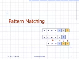
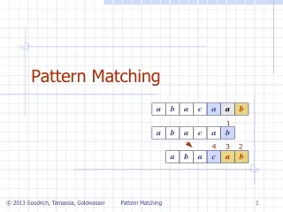
Accelerating Pattern Matching for DPI Author: Jun Mu, Sakir Sezer, Gareth Douglas, Dwayne Burns, Emi Garcia, Mike Hutton and Kevin Cackovic Publisher: SOC Conference, 2007 IEEE International Presenter: Po Ting Huang Date:2009/10/06
Background • hash functions can produce two or more identical keys for distinct input values This inevitable case is referred to as hash collision • perfect hashing is unsuitable for applications for which the string set is incrementally (dynamic) updated • The ideal scheme for DPI must therefore satisfy collision-free storage, efficiency resource utilisation, and flexibility for incremental (dynamic) string-set update.
Introduction • a hybrid fast-pattern-matching architecture for hardware-based DPI is proposed and proof-of-concept implementation based on FPGA technology is presented • The architecture is a hybrid of a Hash and CAM circuit, customized to the deployed DPI pattern-set • DPI:Deep-Packet- Inspection (DPI), based on fast pattern matching became the fundamental function of network surveillance methods and emerging network security systems.
architecture • The hash circuit is comprised of a hash function, comparison circuits and a dual-port embedded memory. • 1.The embedded memory stores the signatures and the corresponding Signature-IDs (S-ID). • 2.The hash function generates a hash key for anyinput string that is used to address the embedded memory to obtain the suspected pattern. • 3.Both the input string and the retrieved pattern are compared. In case of a match the SID of the pattern is flagged to indicate the matching pattern
architecture • As collision resolution, the second, CAM-basedlookup circuit is used. All colliding patterns obtainedfor the first hash-based lookup circuit are nowstored at the second CAM-based lookup circuit. • The same input string used by the hash circuit to obtain hash key are now used by the CAM to obtain the matching signature S-ID • In case of a collision, the first hash-based circuit will produce a valid hash key. However the obtained memory content will not match as it stores only 1 or 2 of the 3, 4 or k matching strings. In this case the second CAM-based circuit will compare the same input string with its entries and output the matching S-ID.
HASH CAM TRADE-OFF ANALYSIS(I) • Embedded memory resources and logic resources are limited Therefore, the trade off must be finely balanced in obtaining the most appropriate hash function, the dimensioning of the hash memory utilisation and the affordable size of the CAM memory. • A good hash function uniformly distributes the keys into the different locations of hash table. Our target is to find a hash function that is not necessarily perfect, but able to scramble the target data strings uniformly into the hash table, i.e. the probability of collision of any given pair of keys has to be 1/n, where n stand for the size of hash table
HASH CAM TRADE-OFF ANALYSIS(II) • Assume that there are m keys to be inserted into a hash table with size of n and l number of keys that are hashed into a single given slot there will be X number of such slots each with l keys hashed in
HASH CAM TRADE-OFF ANALYSIS(III) • The expectation E of X can be expressed as • Equation (1), allows the calculation of the number of slots with l hashed-in keys, e.g. l = 0, 1, and 2. • The percentage of used slots, or load factor L1 of the first RAM block can be expressed using equation(1) for X=1
HASH CAM TRADE-OFF ANALYSIS(IV) • he load factor L2 of second RAM can be expressed as • the number of keys C that needs to be stored in the CAM is the remaining keys C.
HASH CAM TRADE-OFF ANALYSIS(V) • λ is define as the ratio of • Equation (4) can now be expressed as follows:
Simulation(I) • A suitable hash function is derived by simulating a number of known hash functions with the best scrambling properties. For the analysis, 4000 unique 32-bit string patterns have been arbitrarily selected from the latest Snort rule-set • As the hash function, a standard 16-bit Cyclic Redundancy Check (CRC) circuit, based on the original IBM CRC-16 polynomial (0xA001), has been used.
Simulation(III) • Figure-2 shows the two results • (a) the expected results based on equation(6) • (b) the simulated results based on the arbitrarily chosen 4000 snort sub-patterns and the IBM CRC-16 function. • These results also prove that equation (6) can be used to estimate the CAM size for a given m and λ And can be used to obtain λ if the CAM size and m is known
Implementation(I) • CAM circuit using FPGA technology Is restricted by the FPGA LUT resources and entries up to 128 can be build • Because of a targeted line-rate of 10Gbps and datapath of 128-bit, a CAM size of 64 entry and 128 bit data-word has been chosen • Based on the graph in Fig.2 this results λ=0.4. Assuming that m=1000
Implementation(II) • The Hash-CAM circuit has been implemented using Altera Stratix II FPGA technology. The design was described in VHDL and synthesized using Altera Quartus Tools • The post layout synthesis results
end • Of po ting’s presentation