Download
1 / 42
420 likes | 439 Views
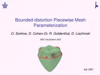
This paper presents a novel approach for parameterization of piecewise meshes with bounded distortion. The algorithm simultaneously performs partitioning and parameterization, resulting in a valid parameterization without self-intersections. The method is simple, fast, and provides a generic scheme for mesh parameterization.

E N D
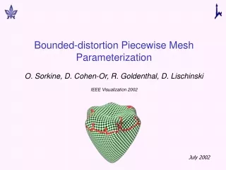
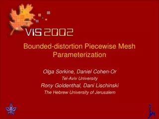
Bounded-distortion Piecewise Mesh Parameterization Olga Sorkine, Daniel Cohen-Or Tel-Aviv University Rony Goldenthal, Dani Lischinski The Hebrew University of Jerusalem
Overview • Parameterization – definition • Applications • Distortion and partition • Previous work • Our approach • Results
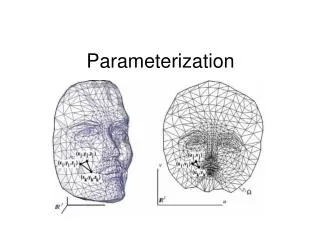
S R3 - given surface D R2 - parameter domain s : D S 1-1 and onto Parameterization - definition
Mesh parameterization • Uniquely defined by mapping the mesh vertices to the parameter domain: U : {v1, v2, …, vn} → D R2 U(vi) = (ui, vi) • No two edges cross in the plane • U is piecewise linear (linear inside each face) • Mesh parameterization mesh embedding
Applications • Texture mapping, 3D painting • Resampling, remeshing • Digital geometry processing • Multi-resolution analysis Using parameterization, we can operate on the 3D surface as if it were flat. Remeshing images taken from “Interactive Geometry Remeshing”, P. Alliez, M. Meyer and M. Desbrun, SIGGRAPH 2002
Distortion and partition • Ideal parameterization is an isometry • General surfaces cannot be embedded without distortion • Surfaces with non-zero Gaussian curvature • Non-disk topology • Partitioning the surface reduces distortion • But: the parameterization is not continuous over the boundaries between the patches of the partition
Previous work • Partition/cut the mesh in pre-process • Interactive user input • Normals bucketing • Region growing from feature curves (Lévy et al. 02) • Flatten each patch by energy minimization • Convex mapping (Floater 97) • Harmonic mapping (Maillot et al. 93, Eck et al 95) • Conformal mapping (Lévy et al. 02, Desbrun et al. 02) • Non-linear Jacobian energy minimization (Sander et al. 01)
Previous work – partial list • Maillot et al. 93 • Eck et al. 95 • Floater 97 • Lévy and Mallet 98 • Lee et al. 98 • Haker et al. 00 • Sander et al. 01 • Gu et al. 02 • Sheffer 02 • Lévy et al. 02 • Desbrun et al. 02 • Zigelman et al. 02 • Bennis et al. 91
Previous framework - discussion • A-priori partition sets lower bound on the distortion cannot comply with preset upper bound on the distortion. • If the distortion is too high, need to subdivide the partition and recompute the parameterization. • Most of the methods cannot prevent triangle flips and global self-intersections (overlaps). • High computational cost (for non-linear optimizations).
Bennis et al. 91 If distortion > threshold stop Surface Plane Works on C2 surfaces sampled on regular grid, even geodesic spacing in both u and v directions.
Our contribution • Parameterization with boundeddistortion • Simultaneous partition and parameterization • Valid parameterization – no self-intersections • Simple and fast algorithm • Generic scheme
Algorithm overview • Greedy algorithm: grow one patch at a time, until no more vertices can be added. • At each step, attempts to flatten the “best” vertex adjacent to the current patch – local criteria. • The distortion of each mesh triangle is guaranteed to be below specified threshold.
Algorithm overview • Select random seed triangle, flatten it. • Maintain a priority queue of the vertices adjacent to the current patch. • Flatten triangles adjacent to current patch: • At each step, take the best vertex off the queue • Check for self-intersections • Stop when no triangles can be added to the patch, and start a new one.
Patch Growth The 3D surface
Patch Growth The 3D surface The planar patch
Patch Growth The 3D surface The planar patch
Patch Growth The 3D surface The planar patch
Patch Growth The 3D surface The planar patch
Patch Growth The 3D surface The planar patch
Patch Growth The 3D surface The planar patch
Patch Growth The 3D surface The planar patch
Patch Growth The 3D surface The planar patch
Patch Growth The 3D surface The planar patch
Patch Growth The 3D surface The planar patch
T T’ In2D In3D The Jacobian distortion metric S D(T, T’) = max{max, 1/ min} max and minare the singular values of the Jacobian [S/s S/t]: • The values max and min are the maximal stretching and shrinking caused to a unit-length vector by the mapping S • We want to equally “punish” stretch and shrink • Any other reasonable metric can be used!
Flattening a single vertex V T1 T2 v1 v2 v t1 t2 t1 t2
Vertex grade components • Maximal distortion caused to the triangles flattened with the vertex. If it’s greater than the threshold, the grade is set to zero and the vertex can’t be flattened in the current patch! • The ratio between patch area and squared perimeter (to create round patches with small boundary length). • Crease angles or other segmentation information. • More criteria…
Checking self-intersections • Local self-intersection – triangle flipping V 1 2 1 2
Checking self-intersections • Global self-intersections: maintain space partition data structure, check the new triangles with the existing boundary edges.
Adding seams • After the patch is finished, we may add seams as a post-process, to benefit from cylinder-like structure.
Adding seams • After the patch is finished, we may add seams as a post-process, to benefit from cylinder-like structure.
Results 11,000 triangles, 1.3 seconds, unoptimized code
3.0 3.0 3.0 2.0 2.0 2.0 1.5 1.5 1.5 1.0 1.0 1.0 Results
Results Bounding the area/perimeter2 ratio... 40,000 triangles, 4 seconds, unoptimized code
Results 100,000 triangles, 9 seconds, unoptimized code
Comparison with global relaxation technique, normal bucketing partition • Conclusions from the comparison: • Much faster • Lower average distortion • Boundary length – sometimes the same, sometimes longer…
Summary • A simple and fast method for surface parameterization • Simultaneously computes the partition and the parameterization • Employs local (generic) criteria rather than global ones • No self-intersections • No explicit control on the number and the size of the patches • Future work: to incorporate segmentation information to gain some “global” properties
Acknowledgements • Israel Science Foundation founded by the Israel Academy of Sciences and Humanities • Israeli Ministry of Science • German Israel Foundation (GIF) • Deutsch Institute