Magneto-Motive Force and Ampere's Circuital Law
150 likes | 207 Views
Understand the principles of Magneto-Motive Force (mmf) and Ampere's Circuital Law in magnetic circuits. Learn about the magnetic field intensity, magnetic induction, and properties of ferromagnetic materials.

Magneto-Motive Force and Ampere's Circuital Law
E N D
Presentation Transcript
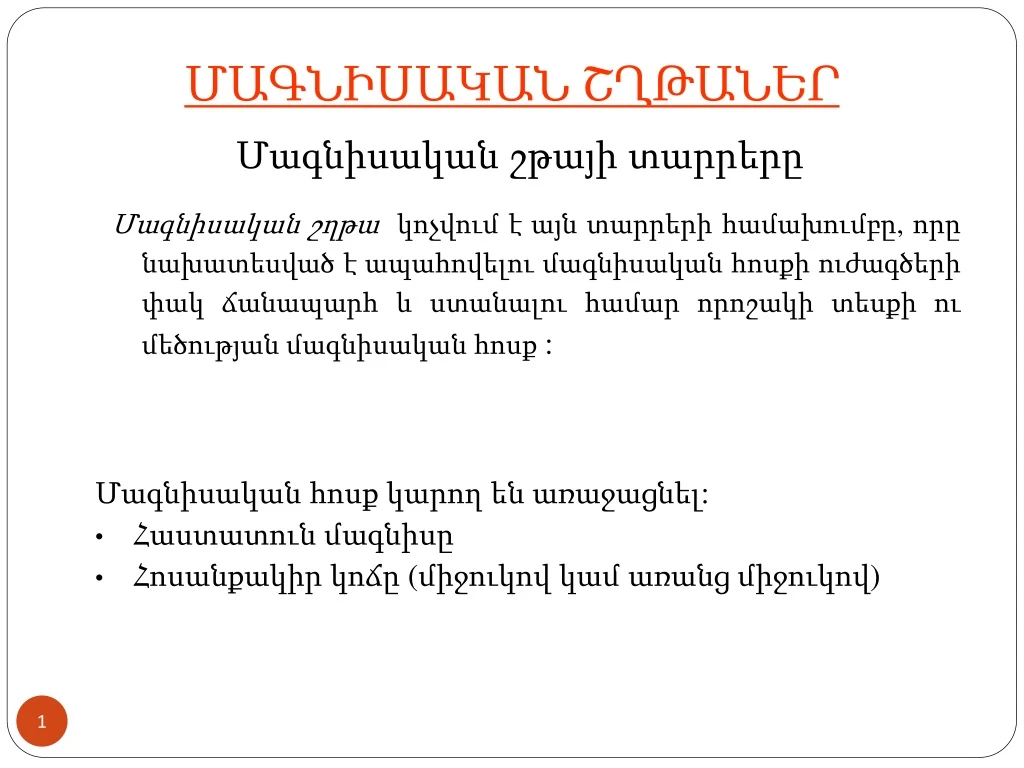
ՄԱԳՆԻՍԱԿԱՆ ՇՂԹԱՆԵՐ Մագնիսական շթայի տարրերը Մագնիսական շղթա կոչվում է այն տարրերի համախումբը, որը նախատեսված է ապահովելու մագնիսական հոսքի ուժագծերի փակ ճանապարհ և ստանալու համար որոշակի տեսքի ու մեծության մագնիսական հոսք : • Մագնիսական հոսք կարող են առաջացնել: • Հաստատուն մագնիսը • Հոսանքակիր կոճը (միջուկով կամ առանց միջուկով)
ՄԱԳՆԻՍԱԿԱՆ ՇԹԱՅԻ ՏԱՐՐԵՐԸ Մագնիսական դաշտի լարվածությունը և ուղղությունը շղթայի յուրաքանչյուր կետում որոշվում է մագնիսական ինդուկցիայի վեկտորով (T - Տեսլա): Մագնիսական հոսքը որևէ S մակերեսի միջով որոշվում է որպես (Wb -Վեբեր)
. .I1 .I2 .I3 Ampere’s circuital law The integral of the magnetic field intensity over any contour (the circulation of the field intensity vector) is equal to the algebraic sum of the currents linked with that contour: (1) - Magneto-Motive Force (mmf) (A) For the magnetic circuit excited by a coil carrying current I and having N turns, F = IN
I R av N Ampere’s circuital law For the most of practical cases of magnetic circuits the integration in Eq.(1) may be replaced with summation, and the Amper’s Circuital Law may be written in a form n – the number of series sections Hk= const – magnetic field intensity in the k-th section k - the length of mean path of k-th section. Ampere’s Circuital Law for the Torus-Form Magnetic Circuit
Properties of Ferromagnetic Materials 1 The magnetic state of any point in magnetic field is well defined by the magnetic intensity vector and the magnetic induction vector having the same direction. If the magnetic field arises in substantial medium, the relationship B = f(H) is given in a form of B = r 0 H = aH where 0 = 4 10-7 H m-1 is the magnetic constant, r - is the relative, and a the absolutemagnetic permeability, of the substance.
B Bm Br H -Hc 0 Hc 10Hc -Br Properties of Ferromagnetic Materials 2 For the most of Materials (Non-Feromagnetic materials)r 1 For Ferromagnetic (or ferrous) materials, r >> 1 Hysteresis Loopof the Ferrous Material Br -Remanence. Hc- Coercitive Force For magnetically soft materials Hc < 0,01-0,05Am-1 For magnetically hard materials Hc > 20 - 30kAm-1.
A1 I N I A1 A2 A2 The Single Path Magnetic Circuit1 The problem most commonly encountered in the design of a magnetic circuit is to find the mmf F = INrequired to excitea magnetic flux (or induction B) within some portion of the magnetic circuit According to the Ampere’s circuital law,
B B2 B1 H1 H2 0 H H The Single Path Magnetic Circuit2 The Magnetic Induction In the Air Gap of the Magnetic Circuit B0 = 0H0 The Magnetic Flux in sections of the Magnetic Circuit = B1A1 = B2A2 = B0 A0 B1= /A1; B2= /A2
i eL ~v N Iron-Cored Inductor 1
2 2 3 1 0 0 1 3 t i 4 4 0 1 i 2 3 4 t Iron Cored Coil = BA According to Ampere’s circuital law Weber-Ampere Characteristic = f (i) of the
Iron-Cored Inductor 1 i • m-Main Magnetic Flux -Leakage Flux ~v e According to KVL E = V = 4.44 f Nm
L r eL 0 e i ~v Idealized iron cored coil Iron-Cored Inductor 2 The leakage fluxcauses a self-induction emf eLin the inductor: According to KVL:
B 2 2 H 0 3 1 i t 0 0 1 3 4 4 1 0 i 2 3 (A) 4 t Iron-Cored Inductor 3 Weber-Ampere Characteristic = f (i) of the cored coil = BA(Wb)