Download
1 / 31
310 likes | 454 Views
Who is in Control? (Enhancing your Simulator using an Extension Language). Sani R. Nassif IBM Research - Austin nassif@us.ibm.com. Hessian-Based Rotational Bounding for Newton Methods (frustratingly effective!). Sani R. Nassif IBM Research - Austin nassif@us.ibm.com. Environment.

E N D
Who is in Control?(Enhancing your Simulator using an Extension Language) Sani R. Nassif IBM Research - Austin nassif@us.ibm.com
Hessian-Based Rotational Bounding for Newton Methods (frustratingly effective!) Sani R. Nassif IBM Research - Austin nassif@us.ibm.com
Nassif. NACDM workshop, 2004 Environment • Semiconductor technology is experiencing an “analysis discontinuity” at the 65 and 45nm nodes. • 2nd and 3rd order effects are starting to become dominant and requiring detailed analysis. • The slowdown in performance gain per node is fueling a desire to better understand (and reduce) existing design margins. • Slowdown also leading to exploration of alternative circuit topologies and design techniques. • Designs continue to grow. • Increasing need for analysis & modeling.
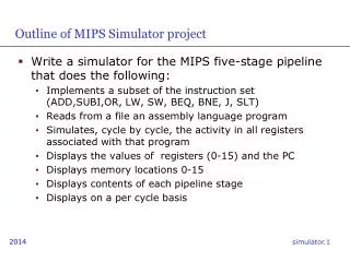
Nassif. NACDM workshop, 2004 input Read Solve Write output Current Simulators • Usually do something like: • Start and read initialization file. • Read input file. • Setup and check simulation problem. • Call solver(s) to perform analysis. • Collect output. • Do some post-processing on the output. • Dump outputs into a file. • Exit. • Simple to code, focuses attention (correctly) on the analysis rather than interfaces. Maybe not so correctly?
Nassif. NACDM workshop, 2004 Simulation: Analysis or Design • Focus on algorithms sometimes detracts from understanding simulator application. • E.g. focus on large scale simulation ignores 99% of total CPU cycles spent in circuit simulators! • Developers seldom think of the efficiency of the simulator as it is applied by the designer! • In fact, developers are seldom aware of the many ways in which simulators get applied. • Until a problem happens… • The fact is that a simulator is a design tool, not just an analysis tool.
Nassif. NACDM workshop, 2004 Impediments • Using a traditional simulator to perform various design tasks presents problems. • Examples: sizing a gate to a specific load, or modeling the setup/hold time of latches. • Two possible outcomes: • Simulator gets enhanced with a new algorithm to solve the specific problem, making it more complex. • Vast amounts of Perl, Python, Awk, and shell scripts get written as wrappers around the simulator to create a “design application” that the design community can use.
Nassif. NACDM workshop, 2004 input input Read Glue Code… Solve Read Write Solve + XXXX output input Write output Read Solve + YYYY Write output Outcomes… Proliferation of simulators with special purpose code. Messy unsupportable inefficient glue code. Solving problem using simplistic “numerical recipes” style algorithms.
Nassif. NACDM workshop, 2004 There is an Alternative • Unwrap the tool into individual components. • Expose each component to an extension language (EL). • Use the EL to script the operation of simulator. • Many extension languages are available: Tcl, Python, Perl, Elk, Lua, Guile… • Even meta-EL tools also exist (SWIG). • Tcl has taken hold in the design automation world (one of the first, had a GUI, easy, simple…).
Nassif. NACDM workshop, 2004 commands Tcl Interpreter Huge library of extensions readily available. Parse Application (Simulator) if read Dispatch resistor file nodes for dcanal Built-in Commands How Tcl Works • Application registers commands with the interpreter which are treated semantically as built-ins.
Nassif. NACDM workshop, 2004 Tcl/Simulator Interface Level Two extremes: • Export the main() routine and use Tcl to pass command line options. • No loss in efficiency, No gain in flexibility. • Explode all data structures and algorithms in the simulator. • Potential loss in efficiency, much gain in flexibility. • (can you imagine LU factorization in an EL!) • There is some appropriate middle ground that defines a level where the efficiency/flexibility tradeoff is optimal for a given application.
Nassif. NACDM workshop, 2004 A Practical Example: LEADER • A Spice-like circuit simulator, under active development at IBM for last 4 years. • Traditional (mostly) algorithms, solvers, models… • A simplified version, dubbed “the simulation substrate” exists with the intent that it be shared. • Open source in industry is difficult! • Techniques also applied in 3 other simulators! • Completely Tcl-based. • Netlist, command and API levels. • Simulation Substrate • Written in C++ • 31578 lines of solver code via abstract interfaces (sparse1.3, slap, …) • 4510 lines of simulator code (simple models only)
Nassif. NACDM workshop, 2004 Netlist as a Program • Hierarchy and parameterization are exactly isomorphic to traditional procedural programming constructs! Parameterization with defaults using procedure arguments Hierarchy implemented using simple name concatenation global L set L 0.065 proc inverter { name input output vdd {wn 1} {wp 1.4} } { global L nmos $name.N –d $output –g $input –s G –w $wn –l $L pmos $name.P –d $output –g $input –s $vdd –w $wp –l $L } vsrc vdd –p vdd –n G –v 0.9 for {set n 0} {$n < 9} {incr n} { inverter INV.$n N_$n N_[expr ($n+1)%9] vdd } WARNING… Source Code Ahead
Nassif. NACDM workshop, 2004 More on Parameterization • Tcl allows extension language variables and internal parameters to be automatically synchronized. Tcl_LinkVar used to link Tcl and C variables… Availability of native file I/O makes tool interactions easy! global R vsrc vdd –p vdd –n G –v 0.9 res R1 –p vdd –n N_a –r @R Res R2 –p N_a –n G –r 2.0 Set pg [open “|xgraph –bb –tk –bg white” w] for {set R 0.1} {$R < 10} {set R [expr $R*1.1]} { dcsolve nodes X puts $pg [format “%6.2f %6.2f” $R $X(N_a)] } Close $pg Simple analysis commands Results returned in native language data structures
Nassif. NACDM workshop, 2004 Stimulus Parameterization • Circuit stimulus can be defined procedurally as well! Very difficult to do in current simulators. • Example: stimulus from files or pipes… proc sinsq_input { t } { set PI2 1.57079632 if {$t < 1} { return 0.0 } if {$t > 2} { return 1.0 } if {$t < 2} { return [expr pow(sin($PI2*(t-1)),2)] } } proc inverter { name input output vdd {wn 1} {wp 1.4} } {…} vsrc vdd –p vdd –n G –v 0.9 vinp vip –p vip –n G –proc sinsq_input inverter X1 vip N_b vdd tranal –step 0.01 –stop 3.0 Tcl procedure used to define input waveform… Simple analysis commands
Nassif. NACDM workshop, 2004 Dynamic Model Support • Models can be defined via EL procedures. • Automatic differentiation and pre-parsing can reduce the cost of interpretation. Tcl procedure used to define the non-linearity… Built in extension does pre-parsing and differentiation proc nonlinear_resistor { a b r0 r1 r2 } { set va [get_voltage $a]; set vb [get_voltage $b]; gcalc { indep va vb; $i = $r0 + $r1*($va-$vb) + $r2*($va-$vb)^2; } return [list $i [deriv i va] [deriv i vb]] } two_term -# $A $B –proc nonlinear_resistor –pars {0 0.1 0.2} Generic 2-terminal elements with parameters
Nassif. NACDM workshop, 2004 Algorithm Control • Having simple default behavior for core algorithms does not necessarily imply that flexibility is lost. Simple commands can hide complex adaptive behavior And shield the user from the internal options & details proc dcsolve { {strategy “default”} } { switch $strategy { “default” if {[_dcsolve –m NEWTON –b 1]} { dcsolve “robust” } “robust” _dcsolve –m HOMOTOPY “silly” { for {set g 1e-3} {$g > 1e-12} {set g [expr $g*0.1]} { option gmin $g; dcsolve –m NEWTON } } Some algorithms can even be implemented at the EL level!
Nassif. NACDM workshop, 2004 Alternative Forms of Netlists • EL allows us to re-target simulator to a completely different paradigm (e.g. brain simulation?). • Because many many problems can look like ODEs. Procedures can map “other” concepts onto circuit forms proc neuron { A B C output {alpha 1.4} } { csrc -# $output G –expr “max(V(A),V(B),V(C),alpha)” cap -# $output G 1e-10 } proc stimulus { A } { isrc -# $A G –pwl {0 0 1e-6 0 2e-6 1e-3 3e-6 0} } proc simulate { interval } { tranal [expr $interval/1000] $interval } ... Same can be done for simulation commands
Nassif. NACDM workshop, 2004 And Finally, GUI Appeal • Interface to a power grid simulator… • (really just a special purpose circuit simulator!) Special purpose widgets added to Tcl for domain-specific visualization!
Nassif. NACDM workshop, 2004 Low Hanging Fruit… • An EL-enabled simulator is, by definition, interactive. • Thoughtful implementation of internal representation can also make it incremental. • Obvious example: integrate simulator with schematic entry! • Far more productive than current batch-style interfaces that exist in commercial design environments.
Nassif. NACDM workshop, 2004 From Analysis to Design • Circuit design often requires meta-analysis and optimization. • Meta-analysis: the composition of multiple simulation results to resolve a design performance question. • Example: determination of latch setup/hold times (one of the core tasks of “library characterization”). • Optimization: the methodical modification of parameters to meet performance targets. • Example: sizing a keeper to reduce noise.
Nassif. NACDM workshop, 2004 Example: Latch Characterization • Latch: state holding element, core of sequential (clocked) digital systems. Latch Data Output Clock Data Tsetup Output Clock Time • Data gets copied to output when clock transitions. • BUT… Data must be stable Tsetup before clock arrives!
Nassif. NACDM workshop, 2004 Latch Behavior vs. Tsetup OK Output Tsetup Changing Tsetup Not OK Clock Data
Circuit, performance, and simulation scripts can be encapsulated. Similar algorithms can be abstracted. Nassif. NACDM workshop, 2004 Zero Finding Binary Search Golden Section Meta-Analysis Example Simulation Setup Performance Definition Latch Circuit Definition
Nassif. NACDM workshop, 2004 Meta-Analysis Using an EL • Power of a complete interactive prototyping environment makes creating meta-analyses very easy. • A modest amount of discipline results in meta-analysis code that is re-usable. • Availability of object oriented extensions to Tcl (incrTcl) helps add the discipline needed when “wrapping” meta-analyses. • Classes also allow for better data hiding when needed.
Nassif. NACDM workshop, 2004 More Complex Analysis • Once circuit & performance are parameterized, complex interactions can be handled via standard packages. • A few key “objects” serve to mediate. • Implemented as Tcl extensions. • Parameter: name, value, range, distribution… • Performance: name, transform…
Nassif. NACDM workshop, 2004 Example: Sampling Create parameters and MonteCarlo sample param P { R1 3 2 4 } { R2 7 5 10 } set NS 100 sample $NS P DATA vsrc vdd –p vdd –n G –v 1.0 res R1 –p vdd –n A –r @R1 res R2 –p A –n G –r @R2 for {set i 0} {$i < $NS} {incr i} { set R1 $DATA($i,0) set R2 $DATA($i,1) dcsolve nodes X puts [format “R1=%.3g R2=%.3g V(A)=%.3g” $R1 $R2 $X(A)] } Create a simple parameterized circuit During simulation loop use samples to re-parameterize circuit
Nassif. NACDM workshop, 2004 And Finally, Optimization • Numerous optimization packages available. • Most expect the objective function to be specified as a callable object. • EL can mediate… • Implement standardized objective function in any language compatible with the optimizer. • Have the standardized objective function call the name of a Tcl procedure. • Return the result of the Tcl procedure. • Reality Check… often optimization is not what we want and “improvement” suffices. The presence of process variability and various forms of model inaccuracy mean that improvement is often more realistically achievable!
Nassif. NACDM workshop, 2004 EL Interface to Optimizer Advanced features like constraints, analytical sensitivities, stopping criteria & error handling are handled in a similar manner to parameters Multiple optimization algorithms can be implemented & wrapped to allow for easy selection Tcl Wrapper for Optimizer Optimizer Parameter Definitions Problem Definition Optimization Algorithm Objective Function
Nassif. NACDM workshop, 2004 Example: Optimization Create parameters that will be optimized Param P { R1 3 2 4 } { R2 7 5 10 } vsrc vdd –p vdd –n G –v 1.0 res R1 –p vdd –n A –r @R1 res R2 –p A –n G –r @R2 proc func { X } { global R1 R2 set R1 $X(0); set R2 $X(1) dcanal nodes Y return [expr pow($Y(A)-0.5,2)] } sqp P func puts [format “optimum at R1=%.3f R2=%.3f” $P(R1) $P(R2)] Create a simple parameterized circuit Create procedure to simulate and return objective function Call optimizer and print result
Nassif. NACDM workshop, 2004 Conclusions • We need to move simulators beyond analysis to become “design” tools. • Traditional simulator architectures make this difficult and inefficient in developer time. • The use of extension languages and careful thought to the level of the EL/simulator interface can improve simulator flexibility. • The integration of sampling, optimization, and other analysis algorithms into the mix will result in an efficient problem solving platform for design applications.
Nassif. NACDM workshop, 2004 Questions?