Download
1 / 41
410 likes | 443 Views
This comprehensive guide introduces key concepts in 3D graphics, from object space to screen space. Topics covered include transformations, polygon matrices, rendering techniques, camera setups, normal computations, and polygon rendering considerations. Learn about perspective transforms, back-face culling, computing normals, dot product calculations, and handling roundoff errors in polygon rendering. Gain insights into rendering techniques such as ray tracing and polygon modeling, with a focus on efficient polygon rendering and normal calculations.

E N D
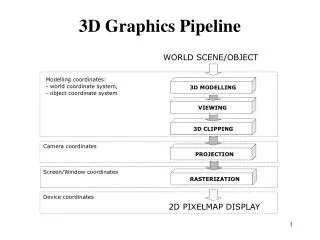
Revisiting the Display Pipeline • Object space • World space • Camera space • Image space • Screen space
Homogeneous Coordinates • 3D Vectors use a 4th, homogeneous coordinate • Usually 1, if not, divide through(4,3,2,1) = (8,6,4,2) • All transformations kept in the form of 4x4 matrices. This keeps the matrices invertible, and all transforms are matrix multiplications.
Building Polygon Matrices • New problem in 3D: Which side of the polygon is the front? • Relative order of vertices in matrix matters • Vertices should appear in counter-clockwise order for right handed systems and clockwise order for left handed systems • Now normal vector will denote the “front”
Analogous Transformation Matrices • The do-everything transform matrix: a b c p Top 9- rotations d e f q p,q,r – perspective g I j r h,k,l - translation h k l s s – overall scaling
Scaling a 0 0 0 0 e 0 0 0 0 j 0 0 0 0 1 a in x-dir e in y-dir j in z-dir Negative values reflect
Translation 1 0 0 0 0 1 0 0 0 0 1 0 h k l 1 shift h in x-dir k in y-dir l in z-dir
Rotations 1 0 0 0 0 cosӨ sinӨ 0 0 -sinӨ cosӨ 0 0 0 0 1 cosӨ sinӨ 0 0 -sinӨ cosӨ 0 0 0 0 1 0 0 0 0 1 About x About z
Rotations cosӨ 0 -sinӨ 0 0 1 0 0 sin Ө 0 cos Ө 0 0 0 0 1 About y-axis Note changes in sines!Necessary for preserving handed-ness
Overall Scaling • Scale factor is last coordinate in last row • s < 1 expands, s >1 contracts • Must “divide through” by s to get last coordinate 1.
Camera/Observer/Eye • Camera position (3D point) • Need perspective of viewer • View direction • Up vector • View direction: • COI: Center of interest • View direction is COI – Eye position
Field of View • Camera position • View Direction & Orientation • Near clipping distance • Far clipping distance • Define: View Frustum: 6-sided volume of world space displayable (truncated pyramid)
Remember Your Trig • SOH CAH TOA • Sin = Opposite / Hypotenuse • Cos = Adjacent / Hypotenuse • Tan = Opposite / Adjacent Hyp Opp Ө Adj
Image Transformation • Right-handed system • Our camera at (-10,0,0) looking down z-axis. • Need to calculate view frustum and project it onto the view window • Change (x,y,z) camera coordinates to (x’,y’) image coordinates
Calculating view distance • Pick an angle for viewing (90 degrees) d = (w/2) / tan(Ө/2) w/2 tangent of 45 degrees = 1 d = w/2, or camera size in unity! d Ө
Calculating x’ Use similar triangle ratios: d is to x’ as t is to x: x’ = dx/t y’ = dy/t t x d x’
Calculating x’ Use similar triangle ratios: d is to x’ as z is to x: x’ = dx/z y’ = dy/z z x d x’ Can approximate by dividing everything by z value.
Perspective Transforms are not Affine! • Vanishing points
Types of Rendering • Rendering = Drawing & filling in polygons • Ray Tracing: Models rays of light • Reverse: Eyes to World • Expensive • Movies (Ice Age) • Polygon Modeling • All Shapes are modeled as polygons • Rounded shapes require more polygons
Polygon Rendering • Triangles (sometimes deal with strips) • Vertices – often exist on multiple triangles • Each triangle needs a normal • Unit vector • Points “out” perpendicular to triangle
Solid Shapes • Is it just adding more polygons? • Must be careful the order in which the polygons are drawn – or the back will cover the front • Most efficient: don’t draw polygons that aren’t visible, then… • Order the visible polygons correctly.
Back-face Culling • Reduce the number of polygons drawn by about half • Need the normal to the polygon • Normal: vector perpendicular to the polygon, facing the same direction as the polygon • Polygon is “facing the camera” if the angle between the camera and the normal is less than 90 degrees
Computing Normals • Cross Product • U x V = (UyVz – UzVy, UzVx – UxVz, UxVy – UyVx) • The vector perpendicular to U and V
Calculating normals • Right-handed: define “front” as counter-clockwise ordering of vertices. • U = v2-v1 • V = v0-v1 • Normal = UxV 1 0 2
Angle between two vectors • Dot product: • U·V = UxVx + UyVy + UzVz • U·V =|U||V|cosӨ • All we care about is whether or not Ө<90: • if U·V<0, then Ө > 90 • if U·V=0, Ө = 90 • if U·V>0,Ө < 90
Does it face camera? • U = camera - v0 • V = Normal • Polygon faces camera if U·V >= 0 1 0 2
Tackling Roundoff • More accurate polygon drawing:Scan Converter • Draw horizontal lines to draw a polygon • Problem: don’t want polygons to overlap, so round down on the right side of the polygon
Horizontal Scanner • Scan object: tells me the left and right x values to draw for all y values in range for the polygon. • For each edge • Find the highest and lowest y values • For each intermediate y, • Find the x point of the intersection • Keep up with the leftmost and rightmost x for this y value over all edges • At the end, you have the leftmost and rightmost x values for each y – then draw horizontal lines
Finding that intersection • You have 2 vertices (x1,y1) and (x2,y2) • The equation of the edge is: y-y1 = m(x-x1) (y-y1)/m+x1 = x • So, x = x1 + (y-y1)/m where m is (y2-y1)/(x2-x1)
Finally,… • For each y, draw a line from left to right • Gives you the filled in polygon with little round-off error
3D Clipping • What about polygons partially in the frustum? • First, clip to a plane: • Polygon is behind plane, ignore it. • Problem: Compute the line segment where the polygon intersects the clipping plane. This becomes a new edge and only vertices in front of the pane are kept.
Hidden-surface Removal • So far: • Back-face culling • Clipping • Doesn’t work for overlapping polygons
More Hidden-Surface Removal • How do you know which objects are in front of others? • Simple ordering • Inefficient • Doesn’t always work • Use Z-Buffer • Collection of depth valueswith pixel color
Hidden surface removal • Painter’s Algorithm: Draw things back to front • Reverse Painter’s Algorithm: Draw things front to back, but don’t draw over a pixel already drawn • Problem: Which point on polygon determines its depth?
Z-Buffering • Or depth-buffering • Store depth of each pixel • Start with all pixels = inf. • Only overwrite if depth is less than current
Final Pipeline • To Draw a polygon: • Check to see if it’s facing the camera • Apply transforms • Project onto the view window • Scan-convert it • Draw the horizontal lines • Use Z-Buffering to determine final pixel-by-pixel coloring
Polygon Rendering • Texture: Picture to paste on the triangles • Shader: Program that determines coloring of triangles • Material: Rendering description including shaders, textures, and lots more • Mesh: Collection of triangles, vertices, and material to render it with • Render Object: Set of meshes defining an object, sometimes uses a skeleton
Types of Shaders • Wireframe – Edges only • Flat – Triangle is single color • Gouraud – Interpolate color between vertices • Phong – takes more lighting models into account (interpolates normals between vertices) • Texture Map – paste picture on triangle • Environment mapping – cube map of environment is put on object to fake shininess