Download
1 / 31
340 likes | 364 Views
Explore the Adept COBRA s600 SCARA 4-axis robot with high-performance options for automation in various operations. Learn about the hardware, work envelope, and interface panel.

E N D
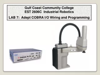
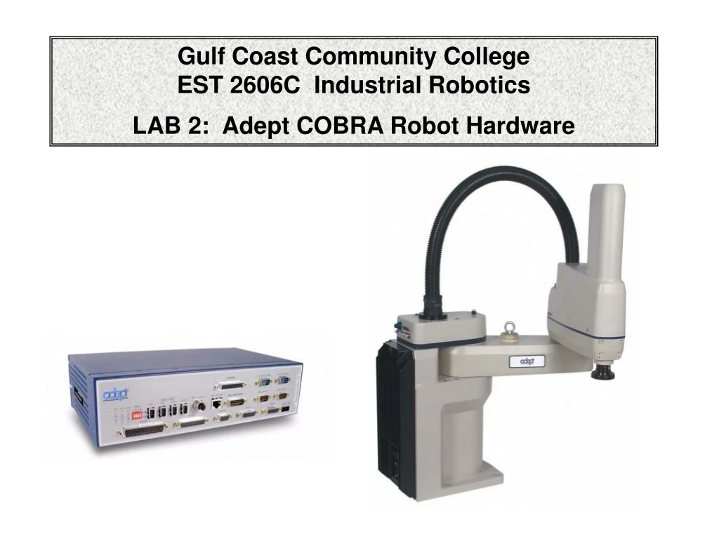
Gulf Coast Community College EST 2606C Industrial Robotics LAB 2: Adept COBRA Robot Hardware
Selected pages from the ADEPT COBRA Manuals
Adept system Hardware Cobra 800 Inverted Viper 650 Quattro 650 Viper 850 Cobra 600 SmartController CX Python Cartesian Viper 1700 Adept PLC Programming
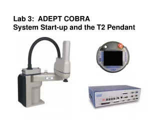
ADEPT Cobra System Pendant Computer Manipulator (ARM) Operator Control Panel SmartController
Adept COBRA s600 Robotic System
SCARA Robot - Adept Cobra s600 The Adept Cobra™ s600 SCARA robot (4-axis robot) is an affordable, high-performance robot system for mechanical assembly, material handling, packaging, machine tending, and many other operations requiring fast and precise automation. The Adept Cobra s600 SCARA 4-axis robot offers maximum flexibility and cost-saving expansion capabilities that are only available with the Adept SmartServo architecture. The Adept Cobra s-series SCARA robots support high-performance options, including conveyor tracking, vision guided motion.
Robot Joints – 4 axis Joint 1: “Shoulder” Joint 2: “ Elbow” Joint 3: “Up/Down” Joint 4: “Wrist roll”
Robot Interface Panel – Back of robot arm 24VDC - for connecting user-supplied 24VDC power to the robot. The mating connector is provided. Ground Point - for connecting cable shield from user-supplied 24 VDC cable. 200/240VAC - for connecting 200-240 VAC, single-phase, input power to the robot. The mating connector is provided. XSLV - for connecting the supplied XSYS cable from the controller XSYS connector. (DB-9, female)
Robot Interface Panel – Back of robot arm (Continued) SmartServo 1/2 - for connecting the IEEE 1394 cable from the controller (SmartServo 1.1) to the robot upper connector (SmartServo 1). The robot lower connector (SmartServo 2) can be used to connect to a second robot or another 1394-based motion axis. RS-232 - used only with Cobra i-series robots, for connecting a system terminal. (DB-9, male) XPANEL - used only with Cobra i-series robots, for connecting the front panel and MCP. XIO - for user I/O signals for peripheral devices. This connector provides 8 outputs and12 inputs.
The Adept SmartController™ CX is a high-performance robot motion controller based on the Adept SmartServo architecture. Its distributed processing architecture improves performance by freeing up 30% of the processor's resources. The Adept SmartController CX features a faster processor and conveyor belt tracking support, and optional vision guidance support. It also features several high-speed communication interfaces, including Fast Ethernet and SmartServo™.
1. Top Three Status LEDs The top three two-color LEDs indicate diagnostic test, power control, and communication status. 2. Bottom Three Status LEDs The bottom three LEDs on the front of the SmartController give the following information about the status of the main controller. 3. SW1 DIP switches The DIP switches define certain configuration settings (including auto boot and user interface). 4. SmartServo 1.1 and 1.2 These ports connect any Adept SmartServo-compatible product to the controller via the IEEE-1394 cable. The 1.1 and 1.2 ports are interchangeable, either one can be used. 5. DeviceNet connector DeviceNet is a field bus for industrial devices. This standard supports a variety of products, including sensors, digital I/O, analog I/O, RS-232, and PLCs. Adept directly supports digital I/O devices and has currently qualified DeviceNet products from Wago and Beckhoff. Other DeviceNet product types, such as keypads and displays, can be controlled using the V+ FCMD program instruction (see the V+ Language Reference Guide for details).
6. Ethernet (Eth 10/100) connector The shielded RJ-45 receptacle that supports 10/100 BaseT Ethernet communications. 7. RS-232 and RS-422/485 connectors These ports support RS-232 and RS-422/485 devices, respectively. See “SmartController Serial I/O Connectors” on page 44 for pin descriptions and locations. 8. XDIO connector This connector includes 20 signal pairs; 8 digital outputs (100 mA max) and 12 digital inputs, including four fast inputs (the first four input signals on this connector are the only input signals that can be configured as fast inputs). The digital outputs are short-circuit protected. This connector also supplies 24 VDC power for customer equipment. See Section 3.8 on page 59 for more information. 9. XUSR connector Provides switch functions for emergency stop (E-Stop) and Manual/Automatic interfaces to external push buttons and other equipment. For example, an external E-Stop can be connected to the XUSR connector. A line E-Stop from other equipment can be connected. A muted safety gate that causes an E-Stop only in Automatic mode is included. Also included are contacts to report the status of E-Stop push buttons and the Manual/Automatic switch.
10. XSYS connector Connects to the PDU3 in a Python linear modules system, to the XSLV connector on a Cobra s-series robot, to the XSLV connector on the sDAI in an Adept Viper robot system, or to the XSLV connector on the sEJI in an AdeptOne with SmartController robot system. 11. XFP connector Connects to the Front Panel. See Section 3.7 on page 49 for information. 12.XMCP connector The optional Adept T1 Pendant plugs into this connector, via the T1 Pendant Adapter cable, which has the mating connector for the XMPC. The SmartController ships with a terminator plug attached to the XMCP connector. The terminator plug must be installed in the absence of a T1, or an MCP. If nothing is connected to the XMCP, then the E-stop circuit is open, and you will not be able to start the system.
Operator Front Panel 1. XFP connector Connects to the XFP connector on the SmartController. 2. System 5V Power On LED Indicates whether or not power is connected to the controller. 3. Manual/Automatic Mode Switch Switches between Manual and Automatic mode. In Automatic mode, executing programs control the mechanism, and the mechanism can run at full speed. In Manual mode, the system limits mechanism speed and torque so that an operator can safely work in the cell. Manual mode initiates software restrictions on robot speed, commanding no more than 250 mm/sec as required by RIA and ISO standards. Please refer to your robot manual for further details. 4. High Power On/Off Switch & Lamp Controls high power, which is the flow of current to the robot motors. Enabling high power is a two-step process. An “Enable Power” request must be sent from the user terminal, an executing program, or the MCP. Once this request has been made, the operator must press this button and high power will be applied.
The Teach Pendant The Adept T2 pendant provides a user interface and teach pendant in an ergonomic and rugged package. The T2 pendant is designed for right-handed and left-handed use. All gripping and holding positions enable comfortable and fatigue-free operation.
Installing the 24VDC Robot Cable Connect one end of the shielded 24VDC cable to your user-supplied 24 VDC power supply. See Figure 4-2. The cable shield should be connected to frame ground on the power supply. Plug the mating connector end of the 24 VDC cable into the 24 VDC connector on the interface panel on the back of the robot. The cable shield should be connected to the ground point on the interface panel.
Connecting Digital I/O to the System
Connecting Digital I/O to the System
Connecting Digital I/O to the System Input Wiring Internal 24VDC supplied by input circuits
Connecting Digital I/O to the System Output Wiring Optio-Isolation User supplied voltage 24vdc Use Relays for switching VAC.
Connecting Digital I/O to the System I/0 Break out cable
Connecting Digital I/O to the System XIO Terminal Block Accessory
Connecting Digital I/O to the System Solenoid kit for pneumatic grippers