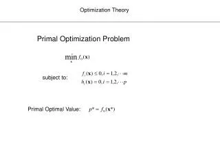
Multi-point Wing Planform Optimization via Control Theory
Multi-point Wing Planform Optimization via Control Theory. Kasidit Leoviriyakit and Antony Jameson Department of Aeronautics and Astronautics Stanford University, Stanford CA 43 rd Aerospace Science Meeting and Exhibit January 10-13, 2005 Reno Nevada.

Multi-point Wing Planform Optimization via Control Theory
E N D
Presentation Transcript
Multi-point Wing Planform Optimizationvia Control Theory Kasidit Leoviriyakit and Antony Jameson Department of Aeronautics and Astronautics Stanford University, Stanford CA 43rd Aerospace Science Meeting and Exhibit January 10-13, 2005 Reno Nevada
Typical Drag Break Down of an Aircraft Mach .85 and CL .52 Induced Drag is the largest component
Wing planform modification can yield larger improvements BUT affects structural weight. Cost Function Simplified Planform Model Can be thought of as constraints
Choice of Weighting Constants Minimizing Maximizing Range using
Structural Model for the Wing • Assume rigid wing • (No dynamic interaction between Aero and Structure) • Use fully-stressed wing box to estimate the structural weight • Weight is calculated based on material of the skin
“Trend” for Planform Modification Increase L/D without any penalty on structural weight by • Stretching span to reduce vortex drag • Decreasing sweep and thickening wing-section to reduce structural wing weight • Modifying the airfoil section to minimize shock Suggested Baseline Boeing 747 -Planform Optimization
Redesign of Section and Planformusing a Single-point Optimization Redesign Baseline Flight Condition (cruise): Mach .85 CL .45
Undesired characteristics The Need of Multi-Point Design Designed Point
Cost Function for a Multi-point Design Gradients
Review of Single-Point designusing an Adjoint method Design Variables Using 4224 mesh points on the wing as design variables Boeing 747 • Plus 6 planform variables • -Sweep • -Span • -Chord at 3span –stations • -Thickness ratio
Optimization and Design using Sensitivities Calculated by the Finite Difference Method f(x)
Disadvantage of the Finite Difference Method The need for a number of flow calculations proportional to the number of design variables Using 4224 mesh points on the wing as design variables 4231 flow calculations ~ 30 minutes each (RANS) Too Expensive Boeing 747 Plus 6 planform variables
Application of Control Theory (Adjoint) GOAL : Drastic Reduction of the Computational Costs Drag Minimization Optimal Control of Flow Equations subject toShape(wing) Variations (for example CDat fixed CL) (RANS in our case)
Application of Control Theory 4230 design variables One Flow Solution + One Adjoint Solution
Key issue for successful implementation of the Continuous adjoint method. Sobolev Gradient Continuous descent path
Design using the Navier-Stokes Equations See paper for more detail
Test Case • Use multi-point design to alleviate the undesired characteristics arising form the single-point design result. • Minimizing at multiple flight conditions; I = CD +a CW at fixed CL (CD and CW are normalized by fixed reference area) a is chosen also to maximizing the Breguet range equation • Optimization: SYN107 Finite Volume, RANS, SLIP Schemes, Residual Averaging, Local Time Stepping Scheme, Full Multi-grid
Mach .90 Mach .84 Mach .85 Isolated Shock Free Theorem “Shock Free solution is an isolated point, away from the point shocks will develop” Morawetz 1956
Design Approach • If the shock is not too strong, section modification alone can alleviate the undesired characteristics. • But if the shock is too strong, both section and planform will need to be redesigned.
Successive 2-Point Design for Sections(Planform fixed) MDD is dramatically improved
Cp at Mach 0.78, 0.79, …, 0.92 • Shock free solution no longer exists. • But overall performance is significantly improved.
Conclusion • Single-point design can produce a shock free solution, but performance at off-design conditions may be degraded. • Multi-point design can improve overall performance, but improvement is not as large as that could be obtained by a single optimization, which usually results in a shock free flow. • Shock free solution no longer exists. • However, the overall performance, as measured by characteristics such as the drag rise Mach number, is clearly superior.
Acknowledgement This work has benefited greatly from the support of Air Force Office of Science Research under grant No. AF F49620-98-2005 Downloadable Publicationshttp://aero-comlab.stanford.edu/http://www.stanford.edu/~kasidit/