Download
1 / 100
1.03k likes | 1.28k Views
Overview of H.264/AVC. 2003.9.x M.K.Tsai. Outline. Abstract Applications Network Abstraction Layer,NAL Conclusion—(I) Design feature highlight Conclusion—(II) Video Coding Layer,VCL Profile and potential application Conclusion—(III). abstract.

E N D
Overview of H.264/AVC 2003.9.x M.K.Tsai
Outline • Abstract • Applications • Network Abstraction Layer,NAL • Conclusion—(I) • Design feature highlight • Conclusion—(II) • Video Coding Layer,VCL • Profile and potential application • Conclusion—(III)
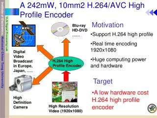
abstract • H.264/AVC is newest video coding standard • Main goals have been enhanced compression and provision of “network-friendly” representation addressing “conversational”(video telephony) and “nonconversational” (storage,broadcast, or streaming) application • H.264/AVC have achieved a significant improvement in rate-distortion efficiency • Scope of standardization is illustrated below
applications • Broadcast over cable, cable modem … • Interactive or serial storage on optical and DVD … • Conversational service over LAN, modem … • Video-on-demand or streaming service over ISDN,wireless network … • Multimedia message service (MMS) over DSL, mobile network … How to handle the variety of applications and networks ?
applications • To address this need for flexibility and customizability, the H.264/AVC design VCL and NAL, structure of H.264/AVC encoder is shown below
applications • VCL(video coding layer), designed to efficiently represent video content • NAL(network abstraction layer), formats the VCL representation of the video and provides header information in a manner appropriate for conveyance by a variety of transport layers or storage media
Network Abstraction Layer • To provide “network friendliness” to enable simple and effective customization of the use of the VCL • To facilitate the ability to map H.264/AVC data to transport layers such as : • RTP/IP for kind of real-time Internet services • File formats,ISO MP4 for storage • H.32X for conversational services • MPEG-2 systems for broadcasting services • The design of the NAL anticipates a variety of such mappings
Network Abstraction Layer • Some key concepts of the NAL are NAL units, byte stream, and packet format uses of NAL units, parameter sets and access units … • NAL units • a packet that contains an integer number of bytes • First byte is header byte containing indication of type of data • Remaining byte contains payload data • Payload data is interleaved as necessary with emulation prevention bytes, preventing start code prefix from being generated inside payload • Specifies a format for use in both packet- and bitstream- oriented transport system
Network Abstraction Layer • NAL units in Byte-Stream format use • byte stream format • Each is prefixed by a unique start code to identify the boundary • Some systems require delivery of NAL unit stream as ordered stream of bytes (like H.320 and MPEG-2/H.220) • NAL units in packet-transport system use • Coded data is carried in packets framed by system transport protocol • Can be carried by data packets without start code prefix • In such system, inclusion of start code prefixes in data would be waste
Network Abstraction Layer • VCL and Non-VCL NAL units • VCL NAL units contain data represents the values of the samples in video pictures • Non- VCL NAL units contain extra data like parameter sets and supplemental enhancement information (SEI) • parameter sets, important header data applying to large number of VCL NAL units • SEI, timing information and other supplemental data enhancing usability of decoded video signal but not necessary for decoding the values in the picture
Network Abstraction Layer • Parameter sets • Contain information expected to rarely change and offers the decoding of a large number of VCL NAL units • Divided into two types • Sequence parameter sets, apply to series of consecutive coded video picture • Picture parameter sets, apply to the decoding of one or more individual picture within a coded video sequence • The above two mechanisms decouple transmission of infrequently changing information • Can be sent well ahead of the VCL NAL units and repeated to provide robustness against data loss
Network Abstraction Layer • Parameter sets • Can be sent well ahead of the VCL NAL units and repeated to provide robustness against data loss • Small amount of data can be used (identifier) to refer to a larger amount of of information (parameter set) • In some applications, these may be sent within the channel (termed “in-band” transmission)
Network Abstraction Layer • Parameter sets • In other applications, it can be advantageous to convey parameters sets “out of band” using reliable transport mechanism
Network Abstraction Layer • Access units • The format of access unit is shown below
Network Abstraction Layer • Access units • Contains a set of VCL NAL units to compose a primary coded picture • Prefixed with an access unit delimiter to aid in locating the start of the access unit • SEI contains data such as picture timing information • Primary coded data consists of VCL NAL units consisting of slices that represent the sample of the video • Redundant coded picture are available for use by decoder in recovering from loss of data
Network Abstraction Layer • Access units • For the last coded picture of video sequence, end of sequence NAL unit is present to indicate the end of sequence • For the last coded picture in the entire NAL unit stream, end of stream NAL unit is present to indicate the stream is ending • Decoder are not required to decode redundant coded pictures if they are present • Decoding of each access unit results in one decoded picture
Network Abstraction Layer • Coded video sequences • Consists of a series of access unit and use only one sequence parameter set • Can be decoded independently of other coded video sequence ,given necessary parameter set • Instantaneous decoding refresh(IDR) access unit is at the beginning and contains intra picture • Presence of IDR access unit indicates that no subsequent picture will reference to picture prior to intra picture
Conclusion—(I) • H.264/AVC represents a number of advances in standard video coding technology in term of flexibility for effective use over a broad variety of network types and application domain
Design feature highlight • Variable block-size motion compensation with small block size • With minimum luma block size as small as 4x4 • The matching chroma is half the length and width
Design feature highlight • Quarter-sample-accurate motion compensation • Half-pixel is generated by using 6 tap FIR filter • As first found in advanced profile of MPEG-4, but further reduces the complexity • Multiple reference picture motion compensation • Extends upon enhanced technique found in H.263++ • Select among large numbers of pictures decoded and stored in the decoder for pre-prediction • Same for bi-prediction which is restricted in MPEG-2
Design feature highlight • Decoupling of reference order from display order • A strict dependency between ordering for referencing and display in prior standard • Allow encoder to choose ordering of pictures for referencing and display purposes with a high degree of flexibility • Flexibility is constrained by total memory capability • Removal of restriction enable removing extra delay associated with bi-predictive coding
Design feature highlight • Motion vector over boundaries • Motion vectors are allowed to point outside pictures • Especially useful for small picture and camera movement • Decoupling of picture representation methods from picture referencing capability • Bi-predictively-encoded pictures could not be used as references in prior standard • Provide the encoder more flexibility to use a picture for referencing that is closer to the picture being coded
Design feature highlight • Weighted prediction • Allow motion-compensated prediction signal to be weighted and offset by amounts • Improve coding efficiency for scenes containing fades one grid means one pixel
Design feature highlight • Improved skipped and direct motion inference • In prior standard ,”skipped” area of a predictively-coded picture can’t motion in the scene content ,which is detrimental for global motion • Infers motion in “ skipped ” motion • For bi-predictively coded areas ,improves further on prior direct prediction such as H.263+ and MPEG-4.
Design feature highlight • Directional spatial prediction for intra coding • Extrapolating edges of previously decoded parts of current picture is applied in intra-coded regions of picture • Improve the quality of the prediction signal • Allow prediction from neighboring areas that were not intra-coded
Design feature highlight • In-the-loop deblocking filtering • Block-based video coding produce artifacts known as blocking artifacts originated from both prediction and residual difference coding stages of decoding process • Improvement in quality can be used in inter-picture prediction to improve the ability to predict other picture
Design feature highlight In addition to improved prediction methods coding efficiency is also enhanced, including the following • Small block-size transform • All major prior video coding standards used a transform block size of 8x8 while new ones is based primarily on 4x4 • Allow the encoder to represent the signal in a more locally-adaptive fashion and reduce artifact • Short word-length transform • Arithmetic processing 32-bit 16-bits
Design feature highlight • Hierarchical block transform • Extend the effective block size for low-frequency chroma to 8x8 array and luma to 16x16 array
Design feature highlight • Exact-match inverse transform • Previously transform was specified within error tolerance bound due to impracticality of obtaining exact match to ideal inverse transform • Each decoder would produce slightly different decoded video, causing “drift” between encoder and decoder • Arithmetic entropy coding • Previously found as an optional feature of H.263 • Use a powerful “Context-adaptive binary arithmetic coding”(CABAC)
Design feature highlight • Context-adaptive entropy coding • Both “CAVLC (context-adaptive variable length coding)” and “CABAC” use context-based adaptivity to improve performance
Design feature highlight Robustness to data errors/losses and flexibility for operation over variety of network environments is enable, including the following • Parameter set structure • Key information was separated for handling in a more flexible and specialize manner • Provide for robust and efficient conveyance header information • Flexible slice size • Rigid slice structure reduce coding efficiency by increasing the quantity of header data and decreasing the effectiveness of prediction in MPEG-2
Design feature highlight • NAL unit syntax structure • Each syntax structure in H.264/AVC is placed into a logical data packet called a NAL unit • Allow greater customization of the method of carrying the video content in a manner for each specific network • Redundant pictures • Enhance robustness to data loss • Enable a representation of regions of pictures for which the primary representation has been lost
Design feature highlight • Flexible macroblock ordering (FMO) • Partition picture into regions called slice groups, with each slice becoming independently decodable subset of a slice group • Significantly enhance robustness by managing the spatial relationship between the regions that are coded in each slice • Arbitrary slice ordering (ASO) • Enable sending and receiving the slices of the picture in any order relative to each other as found in H.263+ • Improve end-to-end delay in real time applications particularly for out-of-order delivery behavior
Design feature highlight • Data partitioning • Allow the syntax of each slice to be separated into up to three different partitions(header data, Intra-slice, Inter-slice, partition), depending on a categorization of syntax elements • SP/SI synchronization/switching pictures • Allow exact synchronization of the decoding process of some decoder with an ongoing video • Enable switching a decoder between video streams that use different data rate, recover from data loss or error • Enable switching between different kind of video streams, recover from data loss or error
Design feature highlight • SP/SI synchronization/switching pictures
Design feature highlight • SP/SI synchronization/switching pictures
Conclusion—(II) • H.264/AVC represents a number of advances in standard video coding technology in term of both coding efficiency enhancement and flexibility for effective use over a board variety of network types and application domain
Video Coding Layer • Pictures, Frames, and Fields • Picture can represent either an entire frame or a single field • If two fields of a frame were captured at different time instants the frame is referred to as a interlaced frame, otherwise it is referred to as a progressive frame
Video Coding Layer • YCbCr color space and 4:2:0 sampling • Y represents brightness • Cb、Cr represents color deviates from gray toward blue and red • Division of the picture into macroblock • Slices and slice groups • Slices are a sequence of macroblocks processed in the order of a raster scan when not using FMO • Some information from other slices maybe needed to apply the deblocking filter across slice boundaries
Video Coding Layer • Picture may be split into one or more slices without FMO shown below • FMO modifies the way how pictures are partitioned into slices and MBs by using slice groups • Slice group is a set of MBs defined by MB to slice group map specified by picture parameter set and some information from slice header
Video Coding Layer • Slice group can be partitioned into one or more slices, such that a slice is a sequence of MBs within same slice group processed in the order of raster scan • By using FMO, a picture can be split into many macroblock scanning patterns such as the below
Video Coding Layer • Each slice can be coding using different types • I slice • A slice where all MBs are coded using intra prediction • P slice • In addition to intra prediction, it can be coded with inter prediction with at most one motion-compensated prediction • B slice • In addition to coding type of P slice, it can be coded with inter prediction with two motion-compensated prediction • SP (switching P) slice • Efficient switching between different pre-coded pictures • SI (switching I) slice • Allows exact match of a macroblock in an SP slice for random access and error recovery
Video Coding Layer • If all slices in stream B are P-slices, decoder won’t have correct reference frame, solution is to code frame as an I-slice like below • I-slice result in a peak in the coded bit rate at each switching point
Video Coding Layer • SP-slices are designed to support switching without increased bit-rate penalty of I-slices • Unlike “ normal ” P-slice, the subtraction occurs in transform domain
Video Coding Layer • A simplified diagram of encoding and decoding processing for SP-slices A2、B2、AB2 is shown (A’ means reconstructed frame)
Video Coding Layer • If stream A and B are versions of the same original sequence coded at different bit-rates the SP-slice AB2 should be efficient
Video Coding Layer • SP-slices is to provide random access and “VCR-like” functionalities.(e.g decoder can fast-forward from A0 directly to frame A10 by first decoding A0, then decoding SP-slice A0-10) • Second type of switching slice, SI-slice may be used to switch from one sequence to a completely different sequence
Video Coding Layer • Encoding and decoding process for macroblocks • All luma and chroma samples of a MB are either spatially or temporally predicted • Each color component of prediction is subdivided into 4x4 blocks and is transformed using integer transform and then be quantized and encoded by entropy coding methods • The input video signal is split into MBs, the association of MBs to slice groups and slices is selected • An efficient parallel processing of MB is possible when there are various slices in the picture
Video Coding Layer • Encoding and decoding process for macroblocks • block diagram of VCL for a MB is in the following
Video Coding Layer • Adaptive frame/field coding operation • For regions of moving objects or camera motion, two adjacent rows show a reduced degree of dependency in interlaced frames but progressive frames • To provide high coding efficiency, H.264/AVC allows the following decisions when coding a frame • To combine two fields and code them as one single frame (frame mode) • To not combine the two fields and to code them as separated coded fields (field mode) • To combine the two fields and compress them as a single frame, before coding them to split the pairs of the vertically adjacent MB into pairs of two fields or frame MB