Semantic Data Modeling in System Design
230 likes | 268 Views
Learn about entity-relation-attribute model, data dictionaries, object models, inheritance, UML notation, and more in system design. Understand structured analysis and design methods with CASE workbenches.

Semantic Data Modeling in System Design
E N D
Presentation Transcript
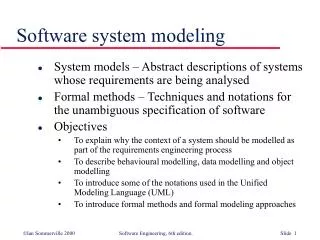
Semantic data models • Used to describe the logical structure of data processed by the system. • An entity-relation-attribute model sets out the entities in the system, the relationships between these entities and the entity attributes • Widely used in database design. Can readily be implemented using relational databases. • In the UML, objects and associations may be used for semantic data modelling.
Data dictionaries • Data dictionaries are lists of all of the names used in the system models. Descriptions of the entities, relationships and attributes are also included. • Advantages • Support name management and avoid duplication; • Store of organisational knowledge linking analysis, design and implementation; • CASE tools can sometimes automatically generate data dictionaries from system models.
Object models • Object models describe the system in terms of object classes and their associations. • An object class is an abstraction over a set of objects with common attributes and the services (operations) provided by each object. • Various object models may be produced • Inheritance models; • Aggregation models; • Interaction models.
Object models • Natural ways of reflecting the real-world entities manipulated by the system • More abstract entities are more difficult to model using this approach • Object class identification is recognised as a difficult process requiring a deep understanding of the application domain • Object classes reflecting domain entities are reusable across systems
Inheritance models • Organise the domain object classes into a hierarchy. • Classes at the top of the hierarchy reflect the common features of all classes. • Object classes inherit their attributes and services from one or more super-classes. these may then be specialised as necessary. • Class hierarchy design can be a difficult process if duplication in different branches is to be avoided.
UML notation • Object classes are rectangles with the name at the top, attributes in the middle section and operations in the bottom section. • Relationships between object classes (known as associations) are shown as lines linking objects. Associations may be annotated with the type of association or special arrow symbols may be used to denote the association type (e.g. inheritance is a triangular white arrowhead) • Inheritance is referred to as generalisation and is shown ‘upwards’ rather than ‘downwards’ in a hierarchy.
Multiple inheritance • Rather than inheriting the attributes and services from a single parent class, a system which supports multiple inheritance allows object classes to inherit from several super-classes. • This can lead to semantic conflicts where attributes/services with the same name in different super-classes have different semantics. • Multiple inheritance makes class hierarchy reorganisation more complex.
Object aggregation • An aggregation model shows how classes that are collections are composed of other classes. • Aggregation models are similar to the part-of relationship in semantic data models.
Object behaviour modelling • A behavioural model shows the interactions between objects to produce some particular system behaviour that is specified as a use-case. • Sequence diagrams (or collaboration diagrams) in the UML are used to model interaction between objects.
Structured analysis and design • Structured analysis and design methods incorporate system modelling as an inherent part of the method. • Methods define a set of models, a process for deriving these models and rules and guidelines that should apply to the models. • CASE tools support system modelling as part of the structured method.
Method weaknesses • They do not model non-functional system requirements. • They do not usually include information about whether a method is appropriate for a given problem. • The may produce too much documentation. • The system models are sometimes too detailed and difficult for users to understand.
CASE workbenches • A coherent set of tools that is designed to support related software process activities such as analysis, design or testing. May be incorporated in an IDE such as ECLIPSE. • Support system modelling during both requirements engineering and system design. • UML workbenches provide support for all UML diagrams and, usually, some automatic code generation. Java, C++ or C# may be generated.
Analysis workbench components • Diagram editors • Model analysis and checking tools • Repository and associated query language • Data dictionary • Report definition and generation tools • Forms definition tools • Import/export translators • Code generation tools
Key points • Semantic data models describe the logical structure of data which is imported to or exported by the systems. • Object models describe logical system entities, their classification and aggregation. • Sequence models show the interactions between actors and the system objects that they use. • Structured methods provide a framework for developing system models.