Electricity
This chapter provides a comprehensive overview of electric circuits, focusing on the creation of electric current through electron motion and the classifications of circuits (closed, open, and short). It explains key concepts such as voltage (electric potential energy), current (which is measured in Amperes), and potential difference. The role of circuit components like batteries, resistors, and capacitors is detailed, along with measurements of voltage using multimeters and voltmeters. Additionally, it discusses energy movements in electric fields involving both positive and negative charges, emphasizing work done in charge movements.

Electricity
E N D
Presentation Transcript
Electricity Chapter 19
Electric Circuits 19.1
Electricity • Electric current is created by the motion of electrons through materials • Electric circuits are complete pathways for current to flow • Closed Circuit – a complete loop of wire which allows current flow • Open Circuit – an incomplete or “open” loop in which current cannot flow. • Short Circuit – an accidental, extra, easier pathway for current to flow
Circuit Components/Symbols Battery Diode Resistor Bulb Capacitor Ground Switch Integrated Circuit Transistor
Current and Voltage 19.2
Electric Potential -- Voltage • Voltage is electric potential energy, measured in volts. DIFFERENCES in the electric potential between two points is what makes electrons move and created current. • Current is the amount of charge flowing per second—measured in Amperes. An Ampere is a very large amount of charge so we usually deal with milli-, micro- and nano-Amperes.
Potential • The electric potentialV, or just the potential, is the potential energy per unit charge • The units of potential are J/C • 1 J/C ≡ 1 V
Potential Difference • The potential difference between points A and B is defined as the change in the potential energy (final value minus initial value) of a charge q moved from A to B divided by the size of the charge ∆ V = VB – VA = ∆ PE / q0 • The potential difference ∆V between two points A and B is the work done per unit charge against the field in moving a unit positive charge q0 from A to B with no acceleration • Potential difference is not the same as potential energy
Potential Difference, cont. • Another way to relate the energy and the potential difference: DPE = q DV • Both electric potential energy and potential difference are scalar quantities • Units of potential difference • V = J/C
Example 1 • A small sphere carrying a positive charge of 10.0 mC is moved against an E-field through a potential difference of +12.0 V. How much work was done by the applied force in raising the potential of the sphere? • Given: q0 = 10.0 mC and ∆V = +12.0 V • Find: W
Example 1 • Solution: Problem Type - Electrostatics/potential difference; this example is about potential, and its definition in terms of work. • The defining relationship between ∆V, q0, and W is Eq. (16.3) (VB – VA) = W(A B)/q W= ∆Vq0= ( + 12.0V)(10.0X 10⁻⁶C) = 120 mJ
Energy and Charge Movements • A positive charge gains electrical potential energy when it is moved in a direction opposite the electric field • A negative charge loses electrical potential energy when it moves in the direction opposite the electric field • If a charge is released in the electric field, it experiences a force and accelerates, gaining kinetic energy • As it gains kinetic energy, it loses an equal amount of electrical potential energy
Energy and Charge Movements • When the electric field is directed downward, point B is at a lower potential than point A • A positive test charge that moves from A to B loses electric potential energy • It will gain the same amount of kinetic energy as it loses in potential energy
Summary of Positive Charge Movements and Energy • When a positive charge is placed in an electric field • It moves in the direction of the field • It moves from a point of higher potential to a point of lower potential • Its electrical potential energy decreases • Its kinetic energy increases
Summary of Negative Charge Movements and Energy • When a negative charge is placed in an electric field • It moves opposite to the direction of the field • It moves from a point of lower potential to a point of higher potential • Its electrical potential energy increases • Its kinetic energy increases • Work has to be done on the charge for it to move from point A to point B
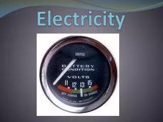
Measuring Voltage • A Multimeter measures voltage/current, depending upon its setting. A reading of +1.5V means that the electric potential at the RED probe’s location is 1.5V HIGHER than that at the BLACK probe’s location
Meters in a Circuit – Voltmeter • A voltmeter is used to measure voltage (potential difference) • Connects to the two ends of the bulb
Creating Voltage • Batteries create potential differences (voltages) through chemical reactions. There are MANY types: • Primary Batteries – NOT rechargeable • “Grocery-Store” Batteries – • Zinc-Carbon – zinc casing with a carbon rod embedded in an electrolyte paste • Alkaline Cells • Transistor Cells • Lantern Batteries • Miniature Batteries -- • Silver-Oxide • Mercury • Lithium
Creating Voltage • Secondary Batteries – ARE rechargeable • Lead-Acid – car batteries • Nickel-Cadmium • Nickel-Metal-Hydride • Photovoltaic – Solar Cells • Fuel Cells – Hydrogen combines with oxygen to create energy and water. Methanol can also be used
Batteries • Two different solid conductors immersed in an active solution (electrolytes) function as a battery • Chemical energy stored in interatomic bonds is converted into electrical-PE as the solution and the electrodes become involved in the chemical reaction • A potential difference that can be used to supply energy and sustain a current in an external circuit is called anelectromotive force – emf • The emf is the voltage measured across the terminals of a source when no current is being drawn from or delivered to it
1.5 V cells + + + + + 1.5 V – – – – – 3.0 V 4.5 V Cells in Series • Voltage across the series-connected battery is the sum of the voltages across each constituent cell Voltages Add Voltages Subtract 1 2 3 • A steady-state current can only exist in a closed circuit, and the same current flows in and out of the load. I is a direct current. • For cells in seriesthe current remains unchanged as it passes in and out of each element V = V1 + V2 + V3 I = I1 = I2 = I3
1 2 3 + + + LOAD 1.5 V – 1.5 V – 1.5 V – Cells in Parallel • Cells attached in parallel form a battery whose voltage is the same as the individual voltages but whose current capacity is the sum of the individual current outputs. V = V1 = V2 = V3 I = I1 + I2 + I3
Measuring Current • Using a multimeter on its current setting, current must be made to flow THROUGH the meter. Thus, using the multimeter as an Ammeter instead of a Voltmeter
Meters in a Circuit – Ammeter • An ammeter is used to measure current • In line with the bulb, all the charge passing through the bulb also must pass through the meter
Electric Current • Whenever electric charges of like signs move, an electric current is said to exist • The current is the rate at which the charge flows through this surface • Look at the charges flowing perpendicularly to a surface of area A • The SI unit of current is Ampere (A) • 1 A = 1 C/s
Electric Current • The direction of the current is the direction positive charge would flow • This is known as conventional current direction • In a common conductor, such as copper, the current is due to the motion of the negatively charged electrons • It is common to refer to a moving charge as a mobile charge carrier • A charge carrier can be positive or negative
Example 2 • A constant downward electron beam transports 3.20 mC of negative charge in 200 ms across the vacuum chamber of an electron microscope. Determine the beam current and the number of electrons traversing the chamber per second. • given: ∆q = 3.20 × 10⁻⁶ C and ∆t = 200 × 10-3 s • find: I and the number of electrons per second
16.0 mA 1.00 × 10¹⁴ electrons/s Example 2 • Solution:Use the definition of current • The current is upward and equal to 1.60 x 10⁻⁵ C/s. The current transfers -1.60 x 10⁻⁵ C/s, and so the number of electrons transported per second, each with a charge of -1.60 x 10⁻⁵ C/s, is
Electrons in a Circuit • The drift speed is much smaller than the average speed between collisions • When a circuit is completed, the electric field travels with a speed close to the speed of light • Although the drift speed is on the order of 10-4 m/s the effect of the electric field is felt on the order of 108 m/s
Resistance • Defined as a measure of how easily (or NOT) current flows through a material. • In a conductor, the voltage applied across the ends of the conductor is proportional to the current through the conductor • The constant of proportionality is the resistance of the conductor • ALL materials have SOME resistance, even wires and batteries, but this is so small we can ignore it. • A multimeter can be set to measure resistance
Resistance • Units of resistance are ohms (W) • 1 W = 1 V / A • Resistance in a circuit arises due to collisions between the electrons carrying the current with the fixed atoms inside the conductor **TOTAL resistance (R) in a circuit determines the current (I) given a certain voltage (V)**
Georg Simon Ohm • 1787 – 1854 • Formulated the concept of resistance • Discovered the proportionality between current and voltages
Ohm’s Law • The current in the circuit varies directly with voltage and inversely with resistance • This statement has become known as Ohm’s Law – rewritten • Ohm’s Law is an empirical relationship that is valid only for certain materials • Materials that obey Ohm’s Law are said to be ohmic
Ohm’s Law • An ohmic device • The resistance is constant over a wide range of voltages • The relationship between current and voltage is linear • The slope is related to the resistance
Ohm’s Law • Non-ohmic materials are those whose resistance changes with voltage or current • The current-voltage relationship is nonlinear • A diode is a common example of a non-ohmic device
Example 3 What is the current through the depicted circuit?
+ – V = 3V I = ½ A + – Example 4 • A small ohmic light bulb is placed in series with two D-cells. The ammeter in series with the bulb reads the current in the circuit (0.50 A) without introducing any appreciable voltage drop across its own terminals. The voltmeter attached to the terminals of the bulb reads the voltage across it (3.0 V) without introducing any appreciable change in the current through the bulb. What is the resistance of the bulb?
Example 4 • Given: At the bulb, V = 3.0 V and I = 0.50 A • Find: R • Solution: Use Ohm's Law. The total voltage across the bulb is the net voltage produced by the batteries, 1.5 V + 1.5 V. 6.0 W
Example 5 • Suppose someone falling out of a tree grabs an overhead power line. The wire has a resistance of 60 microhms per meter and is carrying a dc current of 1000 amps. With hands a meter apart, what is the voltage across him? Will the unfortunate soul get much of a shock? • Given: R/L = 60 mW/m and I = 1000 A • Find: V across 1.0 m
Example 5 • Solution: Use Ohm's Law. The voltage drop across 1.0 m of the line is V = IR = (1000 A) (60 mW/m X 1.0 m) = 0.060 V = 60 mV • You know that you can handle the terminals of a 1.5-V dry cell without feeling any electricity, so 60 mV is much too small a voltage to push a detectable amount of current through a human body.
Temperature Variation of Resistivity • For most metals, resistivity increases with increasing temperature • With a higher temperature, the metal’s constituent atoms vibrate with increasing amplitude • The electrons find it more difficult to pass through the atoms
Types of Resistors • Fixed – have well-defined an unchanging resistance values indicated by the color-codings on the outside **5th band (if present) indicates 5 change in performance after 1000 hours of use**
Types of Resistors • Variable – Potentiometers – allows for smooth changes in the level of resistance in a circuit. Volume control on audio equipment is one application.
Insulators • Insulators are materials in which electric charges do not move freely • Glass and rubber are examples of insulators • When insulators are charged by rubbing, only the rubbed area becomes charged • There is no tendency for the charge to move into other regions of the material
Conductors • Conductors are materials in which the electric charges move freely in response to an electric force • Copper, aluminum and silver are good conductors • When a conductor is charged in a small region, the charge readily distributes itself over the entire surface of the material
Semiconductors • The characteristics of semiconductors are between those of insulators and conductors • Silicon and germanium are examples of semiconductors
Superconductors • A class of materials and compounds whose resistances fall to virtually zero below a certain temperature, TC • TC is called the critical temperature • The graph is the same as a normal metal above TC, but suddenly drops to zero at TC
Superconductors • The value of TC is sensitive to • Chemical composition • Pressure • Crystalline structure • Once a current is set up in a superconductor, it persists without any applied voltage • Since R = 0