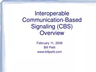
Interoperable Communications Based Signaling
Interoperable Communications Based Signaling. Bill Petit 8 th International Conference on CBTC www.billpetit.com. What I’ll Talk About. What is ICBS? How Does It Work? Where Does It Stand? How Can It Integrate with other Systems? ACSES Overlay on Signal Systems (e.g E/VTMS).

Interoperable Communications Based Signaling
E N D
Presentation Transcript
Interoperable Communications Based Signaling Bill Petit 8th International Conference on CBTC www.billpetit.com
What I’ll Talk About • What is ICBS? • How Does It Work? • Where Does It Stand? • How Can It Integrate with other Systems? • ACSES • Overlay on Signal Systems (e.g E/VTMS)
What is ICBS • A complete vital train-control system capable of operating either as a stand-alone system or as an overlay system on signaled territory (with the eventual goal of being stand-alone) • Based on Signaling Principles and on vital equipment currently in revenue service • Architecture approved and published in AREMA Recommended Practices for C&S • Interoperability (Functions, Messages, Protocols) approved and published • Demonstration completed showing 4 major suppliers capable of operating seamlessly with each other (wayside and carborne)
How Does It Work? • Applies Signaling Philosophy with new technology to maintain the proven safety principles while simultaneously reducing the cost and improving the operational efficiency. • Based on cab-signaling principles • Continuous aspect information provided to engineer that is upgraded or downgraded as needed • Adds onboard database allowing for civil speed enforcement only where needed and profile braking based on grades and specific train braking profiles.
How Does It reduce costs? • Onboard train location system removes need for wayside train location systems • RF Data communications removes need for signals sent through the rails • OnBoard aspect display removes need for wayside signals
How Does It Improve Operating Efficiency • Available Aspects no longer limited by rail characteristics. Multiple new aspects can be defined for closer spacing, better speed management, etc. • Use of Virtual Blocks (not dependent on wayside track circuits) allow shorter headways, closer spacing.
System Architecture • A couple things to keep in mind • Following Examples show various ways of applying the ICBS architecture • Communication paths shown are typical but there is a wide variety of ways that the messages can be routed • Important concept that signaling paradigm concerned with what subsystems need what messages and not how they get there. • Application is RR dependent
Existing cTc Territory Control Office (CAD) Controls and Indications (non-vital) Wayside Bungalow Cab Signal sent through rails
CBS In Dark Territory Control Office (CAD) Controls and Indications (non-vital) Proceed Aspect (vital) Occupying Block RRR.LLL.123456 (vital) Set Switch Normal Profile Calculation to next change point (vital) Switch Locked Normal
CBS (with distributed SLP’s) Control Office (CAD) Controls and Indications (non-vital) Local RF Coverage Local RF Coverage
CBSon Existing Signal Territory Control Office (CAD) Controls and Indications (non-vital) Address of Physical Signal Occupying Block RRR.LLL.123456 (vital) Profile Calculation to next change point (vital) Switch Locked Normal Get aspect of physical signal
Why this Architecture? • Provides operational benefits as part of generic architecture • Following moves in dark territory • Remote control of power switches in dark territory • Mid-block upgrades in current signaled territory • Move toward eventual replacement of wayside signal systems • Common components for passenger and rail systems leading to easier FRA acceptance and funding assistance • Allows railroads to use their own application logic to minimize rule changes and familiarity of operations • Configurable and testable by existing tools
Why this Architecture? • Safety Acceptance • Allows use of safety principles developed over multiple decades of signaling experience • Allows designs to be based on existing vital systems currently proven in revenue service (e.g. processor-based interlocking controllers, processor-based onboard systems) • Systems based on this architecture have been accepted for revenue service with enhanced operational capabilities (e.g. ACSES, ITCS) • Avoids complexity of vital track warrant systems with complex rules and display of onboard text authorities
Background • 6 Manual Parts approved for 2009 AREMA Manual of C&S Recommended Practices
Section 23.2 • 23.2.1 Recommended Functional Requirements of a CBS System. • Define the recommended system functional requirements. • 23.2.2 Recommended RAMS, Environmental and Other Requirements for Signaling Systems Using CBS Architecture. • Define the recommended reliability, availability, maintainability, and safety (RAMS), environmental, electromagnetic compatibility, and quality assurance requirements.
Section 23.3 • 23.3.1 Recommended Design Guidelines for a CBS System • Define the recommended system architecture and interfaces based on conventional signaling principles.
Section 23.4 • 23.4.1 Recommended Communications Protocols for a CBS system • Define the recommended system communication protocol (based on ATCS addressing and datagram) • Capable of being transported over a variety of communications channels (e.g. IP, ITP) • 23.4.2 Recommended Communications Messages for a CBS System • Define the recommended standard messages for communications between CBS subsystems
Section 23.5 • 23.5.1 Recommended Onboard Database Guidelines for a CBS system • Define the recommended structure and content of the onboard database
Project Administration • Funded (partially) by FRA Office of RR Development • Administered through Railroad Research Foundation through a Cooperative Agreement with FRA
Project Administration • Railroad Research Foundation subcontracts for • Project Management – Bill Petit (www.billpetit.com) • Test Environment – Critical Link (www.criticallink.com) • Participating suppliers • Alstom • GETS Global Signaling • Safetran Systems • Union Switch & Signal
Project Goals • Demonstrate overall architecture and interoperablity through adherence to AREMA Manual Parts (and suggest modifications as needed)
What we didn't do • Focused on Interoperability and Architecture and not the following: • Standard ADU • Standard Location Determination System • Compatible with GPS and / or Transponders • Braking Algorithm • Compatible with freight algorithms currently under development by RR's as well as IEEE recommended practices for transit • Specific Communication system • Able to use variety of available systems • CAD • Train order or cTc dispatching
Overall Territory with Each Supplier covering One Section GETS Safetran US&S Alstom
Integration with other architectures • Focus on signaling principles allows ICBS functions to be accomplished by a variety of alternate means • Same overall architecture maintained • Same concept as configuring signal systems differently but maintaining same overall principles.
Compatibility with ACSES • Similar Architectures • Current ACSES uses rail-based cab instead of radio based cab • Current ACSES uses databases uploaded from transponders rather than onboard database • Future Amtrak plans for onboard database • Formats are generally similar • Use of ATCS addressing and datagrams for temporary speed restrictions and positive stop override
Control Office (CAD) Controls and Indications (non-vital) Use Rail-Based Cab Signal Occupying Block RRR.LLL.123456 (vital) Use existing cTc Profile Calculation to next change point (vital) Switch Locked Normal
Compatibility with E/VTMS • For Overlaying on existing signal systems, use the “beacons” used to transmit signal and switch information.
Control Office (CAD) Obtain Signal and Switch Status from E/TMS Beacon Controls and Indications (non-vital) Occupying Block RRR.LLL.123456 (vital) Use existing cTc Profile Calculation to next change point (vital) Switch Locked Normal V/ETMS Beacon Transmitting Signal and Switch Status
Questions / Comments ?(Backup details available at www.billpetit.com/icbs.html) Bill.Petit@ieee.org