Download
1 / 54
1.05k likes | 2.49k Views
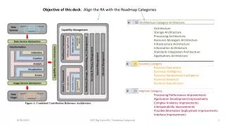
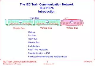
The IEC Train Communication Network IEC 61375 Introduction. Train Bus. Vehicle Bus. Vehicle Bus. Vehicle Bus. History. Choices. Train Bus. Vehicle Bus. Architecture. Real-Time Protocols. Standardization in IEC. Product development and installed base.

E N D
The IEC Train Communication Network IEC 61375 Introduction Train Bus Vehicle Bus Vehicle Bus Vehicle Bus History Choices Train Bus Vehicle Bus Architecture Real-Time Protocols Standardization in IEC Product development and installed base
International Electrotechnical Commission IEC (International Electrotechnical Commission) TC9 (Electrical Traction Equipment) in collaboration with UIC (Union Internationale des Chemins de Fer) set up WG22 (Working Group 22), to define a Train Communication Network railways operators: manufacturers: Chinese Railways Adtranz (CH, DE, SE) DB (Germany) ANSALDO (IT) FS (Italy) CAF (E) JRRI (Japan) Ercole Marelli Trazione/Firema NS (Netherlands) GEC-Alsthom (F, GB, B) RATP (France) Mitsubishi (JP) SNCF (France) Siemens (GB, DE) PKN (Poland) Toshiba (JP) Westinghouse Signals (GB) grouped in the UIC (Union Internationale des Chemins de Fer)
Working Group 22 task TC9 created WG22 in 1988 to define interfaces between programmable equipments, with the aim of achieving plug-compatibility: 1) between vehicles 2) between equipment aboard a vehicle:
Working Group 22 Method of Work Establish the user's requirements (especially UIC) Study existing solutions (Profibus, LON, FIP, MIL 1553, CAN, ...) Build on railways proven solutions supported by railways manufacturers Implement before standardize Solve intellectual property issues Ensure fair access to the technology Test on full scale Define a Conformance test
Two-level Architecture vehicle bus devices The Train Communication Network consists of: • a Train Bus which connects the vehicles (Interface 1) and of • a Vehicle Bus which connects the equipments within a vehicle (Interface 2). Vehicle and train bus are interconnected by a node acting as gateway
Type of Trains WG22 distinguishes two main kinds of trains: Open Trains Example: international passenger trains. composed of vehicles frequently coupled and uncoupled in operation train bus is automatically reconfigured during revenue service FS DB SNCF Example: TGV, ICE, Metro, Suburban trains. Closed Train Sets composed of vehicles not separable in operation. train bus is configured off-line by driver or in the works
Technical Requirements (1989..today) Topology Two-level hierarchy: Train bus connecting Vehicle Busses. Span • Train bus: 850 m (1000m) , 32 nodes. • Vehicle bus: 200 m, 32 stations, 256 simple devices. Medium Twisted wire pair or optical fiber (no coax). A version of the train bus shall use the existing UIC or EP lines. Operation Train bus: automatic configuration of the train bus in less than 1 second, with left-right identification. Traffic • time-critical, short process data (traction control, train control,...) transmited periodically with a deterministic delay of <100 ms from end to end of the train bus, resp. <50 ms on the vehicle bus. • less time-critical messages (diagnostic, passenger information,...) transmitted on demand with reliable flow control and error recovery from end to end. Comply with railways environment, especially IEC 571. Reliability Redundant configuration possible to increase availability.
TCN Bus Candidates for Train and Vehicle Bus Bus Positive Negative IEC/ISA SP50 emerging international field bus not commercially available - still in hot standard debate, complex higher layers. FIP field bus, deterministic, integer, national standard, uncertain future, few supported by EdF, ENEL implementations, costly chips. Profibus process bus, cheap coupling, integer, national standard, uncertain future. Slow, large support in Germany few stations, complex higher layers. MIL 1553 railways and aerospace experience costly (transformers, chips, tools). Insufficient integrity (parity). ARINC 625 aerospace experience costly (transformers, chips, tools). Bitbus simple, widespread slow, dependency on Intel. Manufacturer not willing to open the software. BRELNET, ITDC, railways experience manufacturer does not desire to open it. EKENET (deterministic Ethernet) Factor chips discontinued, not open. railways experience Tornad* relies on standards costly stations, manufacturer not willing to open the physical level, no support CAN, A-BUS simple, cheap, vehicle experience slow, weak, non-deterministic. good concept of higher layers, tools, LON slow, non-deterministic, unsafe. hierarchical architecture.
Use of Commercial Networks Theory: Use of commercially widely available components and software reduce development costs and guarantee long-term availability Reality: There are not many railways-graded network components on the market. Commercial components must be customized to the application. Large volume sellers have little concern for the small railways market Companies in the computer business are less stable than railways firms. Life-time is 5 years for commercial components, 15 years for industrial products, but 30 years for railways - what about the last 15 years ? Therefore: WG22 decided to select only busses which have been railways-proven and which are supported by in-house manufacturing capability.
Evaluation Results • Evaluated busses: BRELNET, CD450, DIN 43322, Profibus, Modiac, IEC Field bus, Tornad, Tornad*, FIP, Factor, Arlic, Ekenet, Bitbus, CAN, ARINC 1553, MICAS, ITDC, ISA SP50. • Only FIP, ARINC 1553, MIL 1553 and MICAS have fast, deterministic response (1 ms) • Most busses failed because of insufficient integrity or lack of redundancy. • Only LON supported a two-level hierarchy (network layer), but lacked real-time response. • Only MICAS met the technical requirements and was already in use in railways. Its modified version was renamed MVB. • The WTB is a modification of DIN 43322, taking over the CD450 experience. • The communication software was designed especially for the TCN, to support a large number of small and simple stations.
Train Bus Traffic train attendant driver's cab diagnostic computer locomotive coaches for destination Y coaches for destination X driving coach Vehicles of different types communicate over the train bus for the purpose of: telecontrol traction control: remote, multiple traction,... 1) vehicle control: lights, doors, heating, tilting, ... 2) diagnostics equipment failures, maintenance information 3) passenger comfort next station, disturbances, connections. seat reservation NOT included: passenger private communications, video. IEC TC9 WG22
Wire Train Bus (WTB) standard communication interface between vehicles node node node main application open trains with variable composition such as UIC trains covered distance 860 m number of nodes 32 data rate 1'000'000 bit/second over shielded, twisted wires response time 25 ms inauguration assigns to each node its sequential address and orientation experience based on DB-bus, FS-ETR450 and SBB Huckepack status fully tested on ERRI train, vehicles in operation
WTB Wiring Uses jumper cables or automatic couplers between vehicles. Fritting (voltage pulses) is used to overcome oxydation of contacts Since there are normally two jumpers, the wiring is basically redundant: The UIC specified a new cable ( 18 pole) compatible with the 13-pole UIC connector
WTB - New UIC Cable The UIC discarded the previous idea of decommissioning existing UIC lines and agreed to introduce an additional shielded wire pair for the Train Bus: 9 5 11 12 7 8 10 6 15 1 20 16 3 4 14 2 X Train Bus wire pair Y according to UIC 558 leaflet However, SNCF and DB could not agree whether to introduce an additional wire pair into the UIC-cable or into the EP-brake cable. The EP cable equips SNCF coaches, but few international coaches have it. However, all recent freight vehicles have it. ERRI tested both media for transmitting data, with no clear superiority.
WTB Nodes Setup and Inauguration Autonumbering of nodes and election of the master within 1,0 s. All nodes know their position in the bus and distinguish right from left. All nodes are informed of the characteristics of all other nodes before regular operation. In case of master failure, any other node takes over.
WTB: The Vehicle Interface WG22 specified the Wire Train Bus as the standard interface for plug-compatibility between equipment located on different vehicles. WTB is intended primarily for open trains (trains with variable composition), such as UIC international trains. WTB considers the requirements of operators, of manufacturers and of the UIC 5R Pilot Group, expressed in leaflet UIC556. Process Data exchanged over WTB are specified in UIC leaflet 556, to permit vehicles of different origin to communicate without ambiguity. Diagnostics messages exchanged over WTB are defined in UIC leaflet 557.
WTB Data Definition - UIC 556 leaflet 40 octets 88 octets reserved for traction octet bit 4 1-4 lock/unlock ep brake 5-8 lock/unlock right doors 0 octet bit 1 1-4 lock/unlock left doors 5-8 lock/unlock right doors 1-2 all left doors locked 2 all right doors locked 3-4 5-6 extend staircase 7-8 unused (11) 1-2 connect loudspeaker to UIC pair 5-6 3 3-4 connect loudspeaker to UIC pair 7-8 5-6 connect microphone to UIC pair 1-2 7-8 connect microphone to UIC pair 3-4 1-2 connect microphone to UIC pair 3-4 4 3-4 connect external right loudspeakers to UIC pair 7-8 5-6 connect external left loudspeakers to UIC pair 7-8 7-8 connect to called vehicle 1-2 connect to calling vehicle 5 3-6 brake not applied 7-8 emergency brake signal 1-2 last vehicle present 6 3-4 tail signal present 5-8 void (11) UIC leaflet 556 defines the semantics of the exchanged variables
What makes WTB so special ? WTB was designed specially for variable consist (UIC) trains. WTB has unique features in industry: autonumbering of nodes (inauguration) and self-configuration failure recovery over two independent lines fritting to overcome oxidation of contacts long transmission distance without repeater (860 m ) over bad quality cables (jumpers, connectors, discontinuities) operation without previous commissioning close following of UIC 556/ UIC557 leaflets The WTB features cost some overhead: two hardware channels and fritting voltage sources special digital signal processor for Manchester decoding unique link layer for inauguration
Vehicle Bus Multifunction Vehicle Bus (MVB) standard communication interface for all kind of on-board equipment power line radio cockpit train bus diagnosis power electronics track signals brakes motors data rate 1'500'000 bits/second delay 0,001 second medium twisted wire pair, optical fibres number of stations up to 255 programmable stations up to 4096 simple sensors/actuators status > 600 vehicles in service
MVB Physical Media • OGF optical fibers (2000 m) • EMD shielded, twisted wires with transformer coupling (200 m) • ESD backplane bus or twisted wires according to RS485 (20 m) Media are directly connected by repeaters (signal regenerators) All media operate at the same speed of 1,5 Mbit/s. devices star coupler optical links optical links rack rack sensors twisted wire segment
MVB In Closed Train Sets The MVB can span several vehicles in a multiple unit train configuration: Train Bus repeater MVB Node devices with short distance bus devices The number of devices under this configuration amounts to 4095. The MVB can serve as a train bus in trains with fixed configuration, up to a distance of 200 m (EMD medium) or 2000 m (OGF medium).
MVB: The Equipment Interface WG22 specified the Multifunction Vehicle Bus as the standard interface to provide plug-compatibility between equipment on board the same vehicle. The data traffic on the MVB is being defined in WG22's Application Subgroup. Each type of equipment is accessed in a standard way, to read its characteristics, set-up its parameters and download it with new programs. The MVB paves the way to interchangeability of equipment and simplified maintenance procedures. The MVB is important for: • small equipment manufacturers (reduce network diversity) • assemblers (wider choice of suppliers, commissioning) • railways operators (reduce maintenance costs and spare parts)
Characteristics WTB: Train Bus MVB: Vehicle Bus Topography open bus, 860m terminated bus, 300m (2000m) Configuration connectable on the track fixed, pre-configured in works Symmetry right/left, front/rear recognition no orientation Addressing relative to master absolute (physical or logical) Configuration at each composition change at installation time Number of stations 32, one (two) per vehicle 256 in the same vehicle Media Shielded Twisted Pair (UIC cable) 240 um fibre & STP & RS-485 Connector 4 x sub-D optical: ST; STP: 2 x sub-D Redundancy line always duplicated line duplicated by default Gross data rate 1.0 Mb/s 1.5 Mb/s Hamming Distance 4 4 (8 on optical fibre) Medium Access cyclic (n x 25 ms) and sporadic cyclic (n x 1 ms) and sporadic Mastership master selected at startup, backups rotating master, backups Link Control source-addressed broadcast source-addressed broadcast Device classes Intelligent nodes Intelligent and simple devices Differences WTB - MVB
TCN architectures Open train 860 m (without repeater) WTB (standard) MVB MVB 0 node 0 vehicle bus 1 vehicle bus 2 vehicle busses (conduction vehicle) (standard MVB) (standard & not) Connected train sets WTB MVB (standard) 1 vehicle bus not standard vehicle bus 200 m (without repeater) Closed train MVB or other (not standard) MVB MVB 1 vehicle bus 0 vehicle bus 200 m without repeater
TCN Availability Concept Wire Train Bus line A line B WTB node (gateway) redundant bus administrator bus bus administrator administrator 1 2 MVB line A line B slave slave slave slave slave slave device device device device device device All media are by default redundant (send on both, receive from one, check other) On MVB, bus mastership is assumed by alternating bus administrators On WTB, any node can assume mastership upon a failure
TCN Integrity Concept -15 -6 • MVB complies with IEC 570-5 integrity class FT2 (10 with er = 10 ) • WTB has an enhanced HDLC encoding allowing a HD of 4 against sync slips • several mechanisms check data plausibility (configuration, timeliness, indefinite) • undetected errors in devices are more likely than on the bus • for this reason, safety protocols developed for 2/3, 1/2 or coded processors, provide time-stamping, authentication and value check over cyclic services. coded diverse triple modular and/or and/or monoprocessor programming redundancy intelligent A A A B C B B devices c c (application F F F F F F F F F 1 2 1 2 programs) untrusted bus dumb devices (no application programming) and/or and/or triplicated sensor/actor simplex sensor/actor duplicated sensor/actor
TCN Fault-Tolerance Concept WTB (duplicated) other vehicles do not notice redundancy Node Node (on-line) (stand-by) MVB (duplicated) actor sensor TCN allows substitution of MVB devices Messages are re-routed to the on-line unit at switchover time. Stand-by WTB nodes takes over through a new inauguration
TCN Bus Traffic Variables Messages short and urgent data items infrequent, sometimes lengthy carrying the trains's state messages reporting events, for: ... motor current, axle speed, operator's • Users: diagnostics, status commands,... • System: initialisation, down-loading, ... Variables are refreshed Messages represent state periodically, no retransmission changes which may not get lost : protocol is needed in case of a protocol recovers transmission transmission error. errors. Periodic Transmission Sporadic Transmission as Process Data as Message Data On-Demand Traffic Scheduled Traffic basic period basic period event time sporadic periodic sporadic periodic phase phase phase phase
Real-Time Protocols stack All busses of the TCN obey to the same operation principles. The Train Communication Network follows the OSI model. All busses share common Real-Time Protocols and Network Management. Messages Variables Application Application Interface Interface Presentation Management TCN Network Real-Time Protocols Session common to all busses Transport Network Link Layer Interface Link Layer Multifunction Wire Train other Vehicle Bus Bus bus Physical Layer
Process Data Exchange: Determinism and Real-Time cyclic cyclic cyclic cyclic algorithms algorithms algorithms algorithms cyclic application application application application poll 1 2 3 4 bus source port master Ports Ports Ports Ports Traffic Periodic Stores List sink sink port port bus bus bus bus bus controller controller controller controller controller bus port address port data Determinism is a concept stretching from application to application. TCN provides a deterministic transmission by cyclic, source-addressed broadcast Applications are supposed to operate cyclically to be deterministic. TCN supplies a freshness information to detect stale data
Message Exchange and Application Interface Functions communicate the same when located in the same or different vehicles Train Bus vehicle node router router vehicle bus bus functions F F F F F F F F F F F F F functions in different functions within the functions within the function on a node vehicles same vehicle same device communicating with an application in another vehicle A defined application interface ensures that applications can be written independently from the communication system
Message Data: Demand-driven traffic The entities exchanging messages are called Application Functions. Each vehicle supports a number of standardized Application Functions. The train bus accesses a vehicle without knowing its internal structure. The Application accesses functions rather than devices . Functions are implemented by one or several vehicle bus devices, or by a node. Train Bus train-vehicle bus gateway Vehicle master Bus passenger info air condition device device device device device sensors/ doors doors sensor bus actors brakes The gateway deduces the device from the function and routes messages.
Supporting Different Vehicle Structures node node node backplane bus train level vehicle bus vehicle bus stations sensor bus sensors & actuators e.g. VME e.g. DIN e.g. MVB Condition: all devices use the TCN's Real-Time Protocols But: where interoperability is needed, only one type of bus shall be used
Gateways: including foreign devices gateway PD-marshalling Converter application application presentation presentation session session Real-Time PV PV Protocols transport transport network network link link link link physical physical physical physical MVB segment foreign segment The protocol conversion requires a common object address space The important is a common data representation and semantics Therefore, a standard object description is needed.
TCN Network Management WTB managed objects agent agent agent MVB SPY agent agent agent Network Management defines a set of services for: • testing and conformance testing manager • commissionning: configuration, routing and marshalling • operation: error and performance monitoring • maintenance: evaluation of error reports
Conformance Test Theory: the TCN is specified in such detail that implementations by different teams, with only the standard documents as a base, are compatible. Reality: Whatever the level of detail, there will be ambiguities and incompatibilities between implementations. Therefore: The first implementation of the TCN has been done jointly by teams of several firms, to ensure that the core specifications are usable. A user group should act as a forum to provide feedback to the standard. Only one software written in a general language (C) should be used as a reference (also for the standard document). This software must be made available to all parties under fair conditions. Conformance testing will be needed when different implementations arise. There is currently no incentive to have different implementations.
TCN Conformance Test The guidelines for Conformance Test, developed at the request of TC9 in Frankfurt, allow to test a device's conformity with the TCN. These tests have been successfully applied to the ERRI test train. Conformance Testing gives a manufacturer the confidence that his product can interoperate with products of other manufacturers Test Generator Test Test Protocol Script Device Under Test Test Analyser
IEC Status The Train Communication Network became an International Standard in 1999. The document was published in September 1999, consisting of the following parts: 1 General 2 Real-Time Protocols 3 Multifunction Vehicle Bus 4 Wire Train Bus 5 Network Management Annex A: Tutorial Annex B: Guidelines for Conformance Test UIC and UITP strongly support TCN. Meanwhile, several firms implement products based on the draft documents. TCN is now the rule in international bidding.
UIC / ERRI test train The European Railways Research Institute (ERRI) conducted a full-scale test of the TCN (at a cost of some 3 Mio US$). SBB SBB DB DB DB FS FS NS NS A composition of the Interlaken-Amsterdam train, consisting of coaches of Germany, Switzerland, Italy and Netherlands served for the tests. It entered revenue service in May 1994 and served until September 1995. The result of these tests have been considered in the TCN documents The ERRI lab test served as a validation and conformance testing tool.
Lessons learned from the ERRI Test Train • operational problems were underestimated, the test had to be lengthened by 1/2 year. • before installing the TCN, the electrical wiring must be harmonised ( battery polarity, connector wiring, earthing, etc..) • the WTB is more limited by reflections from cabling and connectors than by signal attenuation, decoding by a digital signal processor was a must. • initially, recovery from individual node failures was neglected (domino-effect). Handling degraded mode situations make the bulk of the software. • back-up mode (old UIC lines and WTB running in parallel) caused "mirror effect". The application, not the network, must care for this and other "tail-bitings". • for trouble-shooting, means must be introduced to supervise the bus and bring it in a defined state (like assign mastership to various nodes in sequence) • most of the difficult work was in the application programs (mapping server, etc...)
Joint Development Project Five firms joined forces to develop the Train Communication Network •†Siemens Verkehrssysteme (D), •†Ercole Marelli Trazione - Firema (I), •†AEG Schienenfahrzeuge (D), = Joint Development Project JDP •†ABB Henschel (D) and ADtranz •†ABB Verkehrssysteme (CH) Development was shared among the companies. Communication software was ported to different platforms (Intel, Motorola,..). The operation of the train bus node has been demonstrated. Custom Integrated Circuits are being developed by different companies. The JDP prototype is used in the ERRI Train Bus Tests. There are currently some 20 TCN products available from third parties.
TCN Components Available 1) MVB integrated circuits: available freely from silicon manufacturer 2) WTB nodes or Medium Attachment Unit (3 manufacturers) 3) MVB subprint with or without a processor (PBI, IP bus) 4) MVB attachment to PC-card (2 manufacturers) 5) MVB repeater (2 ASICs) 6) tools for configuration and monitoring 7) communication stack (Real-Time Protocols) and documentation. language: "C" or ADA, ported to: Intel 186 Intel 196 Intel 166 Intel 960 Motorola 68040 DOS/Windows The commercial conditions can be negociated directly with any JDP company, since all are in possession of the rights. JDP is considering general distribution and support by independent companies. JDP field a commitment to IEC to supply all customers under fair conditions
TCN Tools Adtranz: MicTools4.2 system configurator application-level bus analyzer programming environment in function block language display and diagnostics editor DUAGON: DT4 test system for data traffic MVB API (Windows 95) D104: same API for vehicle (PC104 board) i.pro.m: CATAI capture, design and simulation of the TCN node emulation and software application interface development network implementation using IPTCN network network integration and commissioning devices and network testing
TCN Openness IEC required that all components necessary to implement the TCN be commercially available to all parties. • There are no intellectual property rights on the TCN • The product manufacturers were required to file a committment to make their technology available under reasonable conditions • Even so, the documents were written so that a third party can implement a compatible TCN without insider knowledge • The MVB integrated circuit was built out of the standard document only • The software has been ported to several platforms
Stability Theory: Standards are stable and are not modified afterwards. Reality: Computer software is not stable. ASICs technologies become obsolete. Bugs and new requirements require corrections and modifications. Every porting to a new platform causes changes. Therefore: An entity must distribute and maintain the TCN over the years. This entity must have an interest in the application and a commitment towards the railways industry and users. Even if parts of the TCN make use of commercial components, maintenance must anyhow be done for the other components. Only railways manufacturers can bring this stability
ROSIN - WP04 Application Subgroup light doors brakes Device: Door control power Made by: Westinghouse air conditionning Year: 1995 Revision: 1998 May 19 Parameters: position, status, indication, ... Universal Maintenance Tool ... Maintenance messages: .... 1996 Jun 25 10:43 23" low air pressure 1996 Jun 26 10:55 09" emergency open 1996 Jun 26 11:01 17" manual reclose .... A 3 years project of the 4th European program finances the standardisation of the application interface among other TCN applications (total 5 Mio ECUs) Goal: vehicle functions are standardized, but can be implemented in different way. railways companies and manufacturers can access the on-board equipment over Internet
Vehicle Functions • doors • traction • braking & antiskid • automatic train control • are identifiable equipment modules (such as doors, • signalling, localisation air-condition or a whole vehicle), made of • radio • control & command electromechanical, hydraulic, pneumatic, ... parts; • driver display • energy • are implemented by one or several electric (static converter) programmable devices, which implement one pneumatic or several functions; hydraulic • diagnostics on-line • may include simple sensors and actors, depot scattered over the train; • log • fire • may consist of subfunctions in a hierarchical fashion; • de-icing • tilting • may communicate with other functions. • active suspension • lights and other utilities • air condition • passenger information audio, entertainment advertisement • toilet • seat reservation
Suppliers using TCN Holec Automation Ansaldo Automation AEG Automation Knorr Electronic Brakes Westinghouse Brakes Brakes IFE Doors Deuta MMI Hagenuk HVAC Selectron Lyss WC Sécheron Tachometer Faiveley Slip/Skid Control, Doors duagon TCN Products and Consulting i.pro.m TCN Products and Consulting
Consulting and Support PC PC PC PC MPB MPB MPB MPB fibres Optical- power supply Electrical Bus Converter Administrator P I I C C B S / / P P A O O U U star coupler Target CPUs (optional) Input/Output (optional) TCN Starterkits (PC based), training and consultancy are available from: duagon (Switzerland) and i.pro.m (Italy)
TCN Projects in Italy Italian Railways Technical Headquarter in Florence fully support TCN and issued, after an experimental period, two specification documents to be used as technical part of contracts: ST FS n° 308514: Nodo di Comunicazione tra Bus di Veicolo e Bus di Treno della rete TCN/TCN* ST FS n° 308031: Telecomando per la trazione FS is leading an ERRI group in charge to extend the UIC 556 leaflet to the locomotives. Rolling stock Manufacturer Description E402B FS Ansaldo-Siemens 40 locomotives 6 MW (option: 50) E412 FS Adtranz Italy 20 locomotives 6 MW (formerly:Tecnomasio E464 FS Adtranz Italy 50 locomotives 3 MW (formerly:Tecnomasio (option 50+ 50+ 50+ 50+ 50) TAF FS Breda-Ansaldo-Firema 50 trains (each train has 4 vehicles, (consortium) 2 motor coaches and 2 coaches) ETR500 FS BREDA-Adtranz- 60 ETR500 Multitensione Ansaldo-Firema (double voltage 3000DC/15.000 AC) Z1 FS COSTAMASNAGA 35 international coaches