Download
1 / 40
540 likes | 2.56k Views
Design and Develop an IGBT Inverter for AC Motor Drive Applications. Done By: Ali Jumah 199900147 Mohammad Salem 199905041 Ahmad Al-Wahedi 200000137 Advisor: Dr. Md Enamul Haque Eng. Ahamd Abdrabou. Project title and objectives. Introduction. The Power Supply.

E N D
Design and Develop an IGBT Inverter for AC Motor Drive Applications Done By: Ali Jumah 199900147 Mohammad Salem 199905041 Ahmad Al-Wahedi 200000137 Advisor: Dr. Md Enamul Haque Eng. Ahamd Abdrabou
Project title and objectives. Introduction. The Power Supply. Implementation of Power Supply. PCB. The Firing Circuit. Implementation of Firing Circuit. dSPACE. Opto-isolator. Implementation of Opto-isolator. The IGBT module. Implementation of IGBT inverter. The System Case. The Simulation. System Mechanism Analyzing the results. Conclusion. Outline
Project Title and Objectives • Design and Development an IGBT Inverter for AC-Motor Drive Applications. • Objectives: • Design and develop an IGBT inverter. • Improving the motor performance. • Simulating the circuit using any simulation software. • Prototyping and testing the circuit. • Participating in team work activities. • Implementing the theoretical background in real applications. • Interacting with industry.
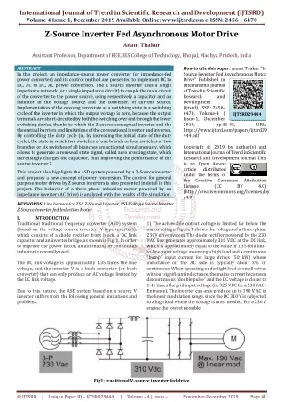
What is IGBT ? • The IGBT inverter (Insulated Gate Bipolar Transistor) main component is the transistor. • It is a very fast switching inverter that is widely used in many applications such as: • Refrigerators. • Electric vehicles. • Lifts. • Oil and petroleum industries. • UPS (Uninterruptible Power Supply).
IGBT Advantages • Low acoustic noise due to high switching frequency. • Low torque ripple. • Low losses associated with switching device. • Low cost driver circuits. • Variable speed operation over a wide speed range results in significant energy savings. • High efficiency. • Smaller size. • Lower overall cost.
Introduction The Schematic Diagram of an AC Motor Drive
Main Power Supply • It is a power supply that was used to feed the IGBT module with 342Vdc. • Supplied by 2 phases line to line AC power supply. • Rectified by a Full-Wave Rectifier. • Filtered by 4 capacitors.
Secondary Power Supply • It is a power supply that was used to feed the Firing Circuit and the Opto-isolator circuit with 15Vdc. • Supplied by 1 phase AC power supply (220Vac). • Transformed by step down transformer. • Rectified by a Full-Wave Rectifier. • Filtered by 2 capacitors.
PCB • PCB( Printed Circuit board). • Printed circuit boards, or PCBs, are used to mechanically support and electrically connect electronic components. • Circuit boards were created in the mid-1930s .
PCB • It consist of : • Base board. • An insulator (usually fiberglass). • Threads of conductive material serving as wires on the base of the board .
PCB Manufacturing • Use a program to built the circuit. • Select each components place. • Print the circuit layout.
PCB Manufacturing • Paste the layout to a copper board. • Put it in closed box with a light source inside for several minutes. • Replace the layout.
PCB Manufacturing • Put the board in solvent (Ferric Chloride) to remove all copper except the circuit. • Drill the board. • Soldering the component to the board.
Firing Circuit • The firing circuit is a circuit that used to keep the IGBT inverter safe from any fault. It also used to control the input signal of the IGBT inverter so that only 2 gates at the same time are working
dSPACE • Controlling system: • Controller board. • Software. • Connections. • Advantages: • Available. • Easy to handle based on software.
Opto-isolator • Helps cut down on ground loops. • Block voltage spikes. • 6 opto-isolator chips were used to build the opto-isolator circuit.
The IGBT Module • It consists of 6 IGBT inverters. • Each arm has two inverters. • Each arm has only one inverter working at a time. • Its output is an AC three phase output.
The System Case • Selecting a flexible and quite hard material (Plastic) • Cutting the plastic as the shape we want, in out case in Cube. • Paste the edges together by using Cl-Acid and angles. • Make a door in the front side or on the top of the case. • Put the whole system inside the case.
The Simulation The Schematic diagram of the simulation
The Simulation Results Simulation Results: Input AC voltage, DC voltage, PWM signals and the Resultant Sine wave Rotor and Stator currents Torque of the motor Speed of the motor
The Spectrum analysis of the signals using PowerGUI tool The spectrum of the input voltage supply of phase a and b with THD of 0.0% The spectrum of the ripple of the DC power supply comes out form the rectifier The spectrum of the resultant sine wave based on the PWM signals with some distortion The spectrum of the three level of PWM signals
System mechanism • An AC input supply of two phases is rectifier through the power rectifier to get a DC voltage goes to the inverter. • Before the DC output of the rectifier goes to the inverter, it should first be filtered to pure DC voltage through 4 parallel capacitors of 330μF with rated voltage of 400VDC. • This DC voltage feeds the IGBT Module.
System mechanism • Then 6 PWM pulses will be generated form the MATLAB through the DSpace device. • These 6 PWM pulses will go to the opto-couplers then to the firing circuit which controls the switching of the IGBT module based on the PWM signal to get the desired sine waves of phase a, b, and c at the output of the inverter module which enters to the motor
System mechanism • The secondary power supply with output voltages of 5Vdc, 15Vdc, and -15Vdc was build to feed the auxiliary circuits of the system such as: the firing circuit and the opto-couplers. • The amplitude of the produced sine waves of phases a, b, and c will depends on the modulation index of the PWM signals. And their frequencies will be equals to the frequency of the reference signal used for modulation.
Testing Results The Main Power Supply • Theoretical result is • Experimental result = • By using a differential probe of scaling to 1/200 • And oscilloscope scaling to 100
Testing Results The Secondary Power Supply
Testing Result PWM signals out of the Opto-couplers Circuit Comparison between Theoretical and Experimental Results Experimental Results
Testing Result The output signal of phase b from the firing circuit to the IGBT module (PWM-3) The negative output signal of phase b from the firing circuit to the IGBT module (PWM-4) Out of three firing circuits, only channel of phase (b) gives an acceptable output signals.
During Testing • Two of the firing circuits were burned. • By rebuilding the burned circuits and checking the whole connections again it was found that one channel of the IGBT Module was short circuited which caused the burn of the two firing circuit. • The IGBT Module was changed, but still there were no acceptable output signals.
Conclusion • Many problems were faced during implementation and testing the system. However, these problems build our personalities and developed our skills to better level of experience. • Some of these problems are: • Out of stock components. • Slow computers with weak CPU processor. • Need to be careful for dealing with high power. • Stuck at the final stage of the project with unknown and unsolved obstacle.
Conclusion • The project developed our skills in three major subjects. • In Power Electronics field: • by designing an IGBT Inverter for AC Motor drive application • In Control field: • Using PWM form controlling the frequency of the Motor • in Power Machinery field: • By learning the mechanism of work of the different machinery such as generators, DC and AC induction motors
Thank you for your listening We are happy to answer your questions