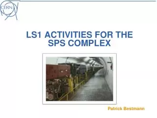
Preparing the SPS complex alignment for future LHC runs
250 likes | 269 Views
Learn about the alignment strategy, planning, and measurements for the SPS complex in preparation for future LHC runs. This presentation covers vertical and horizontal alignment, transfer lines, and strategies for beam quality improvement.

Preparing the SPS complex alignment for future LHC runs
E N D
Presentation Transcript
Preparing the SPS complex alignment for future LHC runs Patrick Bestmann IWAA 2014 IHEP, Beijing, China 13-17.10.2014
Outline • Introduction • Long Shutdown 1 • Measurement and alignment strategy • Planning • Vertical alignment SPS ring • Horizontal alignment of the SPS ring • TI2 & TI8 Transfer lines • TT10 Transfer line P. Bestmann IWAA2014 IHEP, Beijing, China
Introduction P. Bestmann IWAA2014 IHEP, Beijing, China
CERN LS1 • Initially intended for the LHC consolidation • Start of LHC Injector Upgrade Project • Working towards Higher Luminosity • LHC injectors need to push their boundaries to deliver the needed beam quality • 15 Month of SPS shutdown is the unique opportunity to improve the alignment in the whole complex P. Bestmann IWAA2014 IHEP, Beijing, China
Strategy • SPS ring Levelling + alignment 6 w • SPS Sextant 6 Realignment H+V 8 w • SPS Quads horizontal survey 6 w • SPS Quads horizontal alignment 4 w • SPS Dipole + intem. Alignement H+V 20 w • TI2 Transfer line survey and alignment 6 w • TI8 Transfer line survey and alignment 20 w • TT10 Transfer line survey and alignment 12 w • Change of Magnets / Upgrades and installation P. Bestmann IWAA2014 IHEP, Beijing, China
Planning OBSOLETE P. Bestmann IWAA2014 IHEP, Beijing, China
SPS vertical profile • Measured and corrected every year • 6.9km, DNA03 double run with1800 observations LHC P. Bestmann IWAA2014 IHEP, Beijing, China
Sextant 6 • Cumulated ground movements have build a sharp excursion in the vertical profile • Limiting aperture and performance of the machine P. Bestmann IWAA2014 IHEP, Beijing, China
Sextant 6 constraints • Jacks were at the end of the range • Exchange of PU Jacks and additional shimming • TI2 extraction in the center of excursion • Interconnects were kept closed • Restricts roll angle and transversal offsets • Delicate load transfer to jacks • Double actuator hydraulic • Independent adjustment of volume and pressure P. Bestmann IWAA2014 IHEP, Beijing, China
New handling equipment P. Bestmann IWAA2014 IHEP, Beijing, China
Strategy • 3 Step approach to keep track • Relative vertical displacements for focussingQuadrupoles • Reference measurement • Lifting with exchange of jacks and shims • Realignment to new vertical, but initial horizontal position • Alignment of defocussing quadrupoles using the focussing as reference • Alignment of all intermediate components P. Bestmann IWAA2014 IHEP, Beijing, China
Strategy SPS FoDo Lattice QF MB MB MB MB QD MB MB MB MB QF QD MB MB QD MB MB MB MB MB MB QF QF MB MB MB MB MB QD MB MB MB P. Bestmann IWAA2014 IHEP, Beijing, China
Results 92 Quadrupole Magnets aligned P. Bestmann IWAA2014 IHEP, Beijing, China
SPS Horizontal profile • Wire offset measurements • Datum fixed on one Point with radial corridors for some straight sections P. Bestmann IWAA2014 IHEP, Beijing, China
Beam Based Alignment • Very final adjustments to Orbit • Corrector Magnets not strong enough at 450GeV • Measurements done by the operation team during each startup • Cumulated 40 volontary displacements • Change from Q26 to Q20 Optics • All displacements deleted during LS1 • Two iterations done with 10 Magnets in V and 10 in Horizontal direction P. Bestmann IWAA2014 IHEP, Beijing, China
Q20 Orbit • finished P. Bestmann IWAA2014 IHEP, Beijing, China
Transfer Lines TI2 & TI8 • Geologically unstable • Full realignment of TI8 in both planes • Only Quadrupoles of TI2 in both planes • Strategy is basically the same as the one for the SPS or LHC P. Bestmann IWAA2014 IHEP, Beijing, China
TI2 Vertical Profile P. Bestmann IWAA2014 IHEP, Beijing, China
TI8 Vertical Profile P. Bestmann IWAA2014 IHEP, Beijing, China
TT10 Transfer line • Delivering beam from PS to SPS complex • Showed invert heave plus compression racks in the crown and tension/shear cracks at the level of the shoulder P. Bestmann IWAA2014 IHEP, Beijing, China
Measurements P. Bestmann IWAA2014 IHEP, Beijing, China
Work Zone P. Bestmann IWAA2014 IHEP, Beijing, China
Reinforcements P. Bestmann IWAA2014 IHEP, Beijing, China
Future Monitoring • Regular monitoring of Profiles • Installation of new Network points all along TT10 • Installation of a fiber optic permanent monitoring system P. Bestmann IWAA2014 IHEP, Beijing, China
With contributions of Philippe Dewitte, James Ridewood, Richard Francis Morton, Stephan Cettour Cave