Download
1 / 1
10 likes | 111 Views
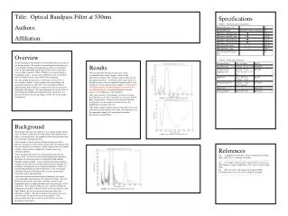
Title: Optical Bandpass Filter at 550nm Authors: Affiliation:. Specifications Table 1—Specifications of our project. Table 2—Total cost of the unit. Overview

E N D
Title: Optical Bandpass Filter at 550nm Authors: Affiliation: • Specifications • Table 1—Specifications of our project. • Table 2—Total cost of the unit. Overview At the beginning of this project, our team defined specific goals for our design to meet. We wanted to maximize optical reflectance at a wavelength of 550nm while minimizing reflectance elsewhere. Also, we determined that our design needed to have a delta that was less than or equal to 150nm. Finally, we set out to design a final product with a cost per unit of $8,000 because we decided that we would be given a cap of $800,000 for funding. Our optical filter design creates a reflectance of over 90% at a wavelength of 550nm. At wavelengths other than 550nm, the maximum reflectance is only 28%. Our team reduced delta to approximately 82nm, which was 68nm better than our goal at the beginning of this project. We limited material use to four stacks of alternating Zinc Sulfide and Lithium Fluoride, which gave us a final cost of $4,612.40 per unit which is $3,387.60 less that what we proposed. • Results • We measured the function of reflectance versus wavelength with 4 stacks (Graph 1) and read the reflectance at 550nm. We used that value to represent our maximum reflectance. To determine how many stacks we thought was necessary, we simulated the filter with 1 stack (Graph 2), 4 stacks, and 10 stacks (Graph 3). From what we set our goals to, we determined that 4 stacks were the optimal amount. To find the thicknesses for the layers, we used equations stated in Table 1. • The main weakness of our design is a result of it using four different stacks. The evaporation of each layer must be done very precisely to ensure correct construction of the final product. As the number of layers increase, the probability of mistakes increases. • The design could be improved given more time to research different materials and how they work. Our reflectance can be improved to about 100% and the delta could be minimized to around 50nm. • Background • This project will allow the military to use a higher quality optical filter. It will be a great benefit to the soldiers who depend on the filters. Our design solves the problem of filters having filters with low reflectance and large deltas[1]. • Our team has worked together to design sunglasses used by Russian astronauts in order to block out harmful UV radiation from the sun and other celestial bodies. Many similar filters are used for satellites and aeronautical equipment to enable long range communication[3]. • Our team began this project by setting specific goals for our design. Next, we used a spectral response program in Matlab to plot index of refraction against wavelength for both Lithium Fluoride and Zinc Sulfide. Using a formula that related material thickness to the index of refraction and reflected wavelength, we obtained a starting point for our experimentation[2]. Finally we used the Matlab program to plot reflectance versus wavelength, and altered the layers’ thickness until we achieved maximum reflectance with a minimum delta. • Our team evaluated our final design by looking at reflectance, cost, bandwidth, and reflectance not centered at 550nm. We used Matlab to measure the reflectance at 550nm, and measured bandwidth (delta) by finding the difference in wavelengths at 50% reflectance. We evaluated reflectance not centered at 550nm by finding the next highest reflectance peak in the spectrum of visible light. Finally, the cost was measured using the values and equations in Table 2. We measured these specifications because they were directly tied to our goals for this project. Our measurements show that we met the goals that we set at the beginning of this project. References [1] C. Bunting. Case Study 1 of the Actipad System. OSU’s REAL LIFE Project. [Online]. Available: http://ecen3613.okstate.edu/Resources/case_studies/CSOne.htm. [2] F. T. Ulaby, Fundamentals of Applied Electromagnetics, 2001 Media ed. Upper Saddle River, New Jersey: Prentice Hall, 2001. [3] Barr Associates, Inc. Innovator in Optical Filter Technology. Barr Associates, INC. [Online]. Available: www.barrassociates.com/applications.php?app=defense