Download
1 / 48
490 likes | 555 Views
Understand manual gearbox clutches, their construction and operation, including key components like flywheel, disc, and pressure plate. Learn how clutches engage, disengage, and transmit power.

E N D
CLUTCH COMPONENT AND OPERATION
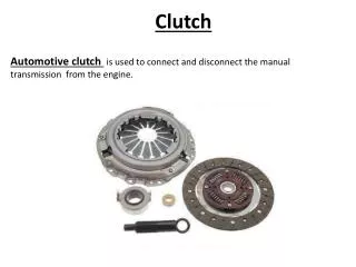
INTRODUCTION • Manual gear box require a clutch to engage or disengage the engine torque • If vehicle had no clutch, engine power will always connected to gear box and engine would dies off every time the vehicle was brought to a stop. • Clutch located between gear box and engine to provides a mechanical coupling • Driver operates the clutch through a linkage that extends from the passenger compartment to the bell housing of the gear box
Clutch Function Can be disengaged – allow engine cranking and permits engine run freely Allow the driver to shift into various gear as the clutch is disengaged Slip momentarily during engagement – to provides smooth engagement and reduce shocks on power train component Transmit power from engine to transmission / transaxle
Clutch component and construction Clutch disc Clutch cover clip Clutch release fork flywheel Release bearing Clutch release bearing hub clip
Clutch basic construction and operation • Consist of three basic parts – flywheel, friction disc and clutch cover assembly • Flywheel and clutch cover assembly are the driving member and attached to the engine crankshaft • Clutch cover consist of pressure spring and pressure plate and bolted to the flywheel • Spring provide force to hold friction disc against the flywheel during engagement
Clutch basic construction and operation • During engagement, driven member is squeezed against the two driving members • The driven member connected to the transmission / transaxle input shaft
Clutch basic construction and operation • As the clutch disengaged, the drive members turn independently and engine power is disconnected from the transmission • When clutch is engaged, the pressure plate moves towards the flywheel and the clutch disc is bound between two revolving drive members and forced to turn at the same speed.
Clutch main component Flywheel • The main driving member of clutch and usually made from nodular cast iron that has high graphite content to lubricate the engagement of the clutch. • Provides some absorption of torsional vibration of crankshaft and inertia to rotate the crankshaft through the four strokes. • Rear surface of flywheel is a friction surface machined very flat to ensure smooth clutch engagement.
Clutch main component Flywheel Plain bolt holes Threaded bolt holes Pilot bushing Dowel pin Facing for clutch disc
Clutch main component Flywheel • There two sets of bolt holes drilled into it. The inner set is used to fasten the flywheel to crankshaft, and outer set provides a mounting plate for the pressure plate assembly. • Bore in the center of flywheel and crankshaft holds the pilot bushing, which supports the front end of the transmission input shaft
Clutch main component Clutch disc • Receives the driving motion from flywheel and pressure plate assembly and transmits the motion to transmission input shaft. • Two types of friction facings. • 1. Mold friction facings – able to work with greater pressure plate loading force without damage • 2. Woven friction facings – used when additional cushioning action is needed for clutch engagement.
Clutch main component Clutch disc • Clutch disc is designed to absorb crankshaft vibration, abrupt clutch engagement and driveline shock. • Material that molded or woven into facings was predominantly asbestos. • Particles of cotton, brass, rope, and wire are added to prolong the life of the clutch disc and provide torsional strength.
Clutch main component Clutch disc
Clutch main component Clutch disc • facings are riveted to wave springs (cushioning springs) to eliminate chatter when clutch is engaged and reduce clutch disc sticking to flywheel pressure plate surfaces when the clutch is disengaged. • Torsional coil springs allow the disc to rotate slightly in relation to the pressure plate while they absorb the torque forces and stop pins limit this torsional movement to approximately 3/8 inch.
Clutch main component Pilot bushing • Support the outer end of the transmission's input shaft and splined to clutch disc to transmits power from the engine to the transmission. • Keep the transmission input shaft in position and keep clutch disc in center of flywheel
Clutch main component Pressure plate assembly • Purpose of the pressure plate assembly • 1. squeeze clutch disc onto flywheel with sufficient force to transmit engine torque efficiently. • 2. move away from clutch disc so clutch disc can stop rotating • Two types of pressure plate assemblies – coil springs type and diaphragm spring of the pressure plate assembly
Clutch main component Pressure plate assembly with coil spring • Uses coil springs and release levers to move pressure plate back and forth. • Springs pressure help to hold pressure plate tightly against the clutch disc and flywheel.
Clutch main component Pressure plate assembly with coil spring
Clutch main component Pressure plate assembly with coil spring • Release levers mechanism release holding force of springs. Has two pivot points • 1. one pivot points attaches the lever to pedestal that cast into the pressure plate • 2. other point to a release lever yoke that bolted to the cover
Clutch main component Pressure plate assembly with coil spring
Clutch main component Pressure plate assembly with coil spring • To disengage the clutch, release bearing pushes the inner ends of the release levers toward the flywheel. • Yokes act as fulcrums for the levers and the outer ends of release levers move backward and pull pressure plate away from clutch disc. • When clutch pedal is released and release bearing move backward, stored energy from the compressed coil springs push the pressure plate and clutch disc against the flywheel with sufficient force to resist slipping.
Clutch main component Pressure plate assembly with coil spring • Advantages of pressure plate assemblies that use coil springs • 1. cleanly disengage the clutch at high engine speeds because of high force exerted by pressure plate springs • 2. offer great flexibility and can be used on various applications since the coil springs can be changed to increase or decrease pressure plate holding force.
Clutch main component Pressure plate assembly with diaphragm spring • Use cone-shaped diaphragm spring between pressure plate and pressure plate cover to move the pressure plate back and forth. • Diaphragm spring yields when pressure is applied to it and back to its original shape when pressure is released. • Center portion of diaphragm spring is slit into numerous fingers that act as release levers.
Clutch main component Pressure plate assembly with diaphragm spring
Clutch main component Pressure plate assembly with diaphragm spring
Clutch main component Pressure plate assembly with diaphragm spring • Diaphragm pivots over the pivot ring. The outer rim forces the pressure plate against the clutch disc so clutch is engaged to the flywheel. • As release bearing pushes inner ends (fingers) of diaphragm spring that pivots over the fulcrum ring, its outer rim moves away from flywheel. • The retracting springs pull pressure plate away from the driven disc and disengage the clutch.
Clutch main component Pressure plate assembly with diaphragm spring • Advantages of pressure plate assemblies that use diaphragm springs • 1. Compactness • 2. less weight • 3. Fewer moving parts to wear out • 4. Little pedal effort required from the operator • 5. Provide balanced force around the pressure plate • 6. Clutch slippage is less likely to occur. Mileage builds because force that holding the clutch does not change throughout its service life.
Clutch main component Clutch release bearing • Release bearing mounted on an iron casting called a hub, which slides on hollow shaft in front of transmission housing. • Also called throwout bearing, usually sealed and prelubricated ball bearing • Function – to smoothly and quietly move the pressure plate release levers or diaphragm spring through the engagement and disengagement process.
Clutch main component Clutch release bearing
Clutch main component Rotating release bearing • Enough tension is applied to clutch control cable to keep a constant light pressure against the release bearing • As a result it kept in contact with the release levers or diaphragm spring of the rotating pressure plate assembly.
Clutch main component Clutch fork • Forked lever that pivots on a ball located in an opening in the bell housing
Clutch main component Clutch fork • Forked end slides over the hub of release bearing and small end protrudes from the housing and connects to clutch linkage and clutch pedal • Moves the release bearing and hub back and forth during engagement and disengagement
Clutch main component Clutch linkages • Series of parts that connects clutch pedal to clutch fork. • Through clutch linkage, operator controls engagement and disengagement of clutch assembly smoothly with little effort • There are two type of clutch linkage • 1. mechanical type • 2. hydraulic type
Clutch main component Mechanical clutch linkages • Mechanical clutch linkage can be divided into two types: • 1. shaft and lever linkage • 2. cable linkage • Shaft and lever clutch linkage consists of various shafts, levers, adjustable rods, and pivots that transmit clutch pedal motion to the clutch fork
Clutch main component Mechanical clutch linkages
Clutch main component Mechanical clutch linkages • Cable linkage can perform the same controlling action as shaft and lever linkage but with fewer parts. • This system does not take much space. It has advantage of flexible installation so it can be routed around the power brake and steering units • Upper end is connected to top of clutch pedal arm and lower end is fastened to clutch fork. It designed with a flexible outer housing that is fastened at the fire wall and the clutch housing.
Clutch main component Mechanical clutch linkages
Clutch main component Hydraulic clutch linkage • Clutch assembly is controlled by a hydraulic system where hydraulic (liquid) pressure transmits motion from one sealed cylinder to another through a hydraulic line. • Hydraulic pressure that developed by master cylinder reduces pedal effort and provides precise method of controlling clutch operation • Brake fluid commonly used as hydraulic fluid in hydraulic clutch systems
Clutch main component Hydraulic clutch linkage
Clutch main component Hydraulic clutch linkage • Main component of hydraulic clutch • 1. clutch master pump • 2. reservoir • 3. clutch sleeve cylinder • 4. pipe line • Basically the operation are same as hydraulic brake system
Clutch main component Hydraulic clutch linkage – master pump
Clutch main component Hydraulic clutch linkage – master pump operation • As pushrod moves, piston and primary cup closed the inlet port to develop hydraulic pressure and transfer the motion to sleeve cylinder • Piston return spring holds the primary cup and piston in the fully released position • Snap ring restricts piston travel. Secondary cup at snap ring end of the piston stops hydraulic fluid from dripping into the passenger compartment
Clutch main component Hydraulic clutch linkage – sleeve cylinder
Clutch main component Hydraulic clutch linkage – sleeve cylinder • As the pressure increase inside the system, it caused the piston sleeve move forward and push the clutch fork • When clutch pedal is released all the related spring in the system will forced the pistons and fork return to original position and clutch will engaged • Fluid will return to fluid reservoir