Download
1 / 6
60 likes | 144 Views
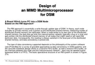
Adaptive signal processing is crucial for advanced radar and communications systems, requiring advanced semiconductor technologies and parallel architectures. This design supports adaptive antenna array beamforming and Doppler spectral filtering applications by calculating system output using signal and weight vectors. The core algorithm involves real-time inversion of a N-by-N matrix and can be solved in various computationally less complex ways. Includes operational structure represented in Figure Y1.

E N D
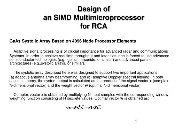
Design ofan SIMD Multimicroprocessorfor RCA GaAs Systolic Array Based on 4096 Node Processor Elements Adaptive signal processing is of crucial importance for advanced radar and communications Systems. In order to achieve real time throughput and latencies, one is forced to use advanced semiconductor technologies (e.g., gallium arsenide, or similar) and advanced parallel architectures (e.g.,systolic arrays, or similar). The systolic array described here was designed to support two important applications : (a) adaptive antenna array beamforming, and (b) adaptive Doppler spectral filtering. In both cases, in theory, the system output is calculated as the product of the signal vector x (complex N-dimensional vector) and the weight vector w (optimal N-dimensional vector). Complex vector x is obtained by multiplying N input samples with the corresponding window weighting function consisting of N discrete values. Optimal vector w is obtained as:
Symbol R refers to the N-by-N inverse convariance matrix of the signal with the (i,j) -th component defined as: and symbol refers to N-dimensional vector which defines the antenna direction (in the case of adaptive antena beamforming) or Doppler peak (in the case of adaptive Doppler spectral filtering). Symbols M and v represent scaled values of R and s, respectively. In practice, the scaled values M and v may be easier to obtain, and consequently the remaining explanation is adjusted. The core of the processing algorithm is the inversion of a N-by-N matrix in real time. This problem can be solved in a number of alternative ways which are computationally less complex. The one chosen here includes the operations explained in Figure Y1a.
Positive semi definite matrix M can be defined as: M = U D UT Matrices U and D are defined using the formula: which is recursively updated using the formula: a. Figure Y1: Basic Operational Structure Legend: SAA1 – Cells involved in root covariance update, and the first step of back substitution; SAA2 - Cells involved in root covariance update, and in both steps of back substitution; U – Lower triangular matrix with unit diagonal elements D – Diagonal matrix with positive or zero diagonal elements b – A scalar initially set to 1 K – Iteration count.