Download
1 / 66
1.11k likes | 2.03k Views
ASCE 7-05 Seismic Provisions. A Beginner’s Guide to ASCE 7-05 Dr. T. Bart Quimby, P.E. Quimby & Associates www.bgstructuralengineering.com. Earthquake Protective Design Philosophical Issues. High probability of “Failure”

E N D
ASCE 7-05 Seismic Provisions A Beginner’s Guide to ASCE 7-05 Dr. T. Bart Quimby, P.E. Quimby & Associates www.bgstructuralengineering.com ASCE 7-05 Seismic Provisions - A Beginner's Guide to ASCE 7-05
Earthquake Protective Design Philosophical Issues • High probability of “Failure” • “Failure” redefined to permit behavior (yielding) that would be considered failure under other loads. • High Uncertainty • Importance of Details “In dealing with earthquakes we must contend with appreciable probabilities that failure will occur in the near future. Otherwise, all the wealth of the world would prove insufficient… We must also face uncertainty on a large scale… In a way, earthquake engineering is a cartoon… Earthquakes systematically bring out the mistakes made in design and construction, even the minutest mistakes.” Newmark & Rosenblueth ASCE 7-05 Seismic Provisions - A Beginner's Guide to ASCE 7-05
Hazard Levels Performance Levels • Incipient Collapse • Life Safety • Immediate Reoccupancy • Fully Operational • Occasional • 50% in 50 years • Rare • 10% in 50 years • Very Rare • 5% in 50 years • Max Considered • 2% in 50 years ASCE 7-05 Seismic Provisions - A Beginner's Guide to ASCE 7-05
Design Objective Defined • A specific performance level given a specific earthquake hazard level • Stated basis of current codes: • Life safety (+some damage control) at 10% in 50 year event (nominally) ASCE 7-05 Seismic Provisions - A Beginner's Guide to ASCE 7-05
Purpose of the Provisions FEMA 302 Section 1.1 “The design earthquake ground motion levels specified herein could result in both structural and nonstructural damage. For most structures designed and constructed according to these Provisions, structural damage from the design earthquake ground motion would be repairable although perhaps not economically so. For essential facilities, it is expected that the damage from the design earthquake ground motion would not be so severe as to preclude continued occupancy and function of the facility.” “For ground motions larger than the design levels, the intent of these Provisions is that there be a low likelihood of structural collapse.” ASCE 7-05 Seismic Provisions - A Beginner's Guide to ASCE 7-05
ASCE 7-05 Seismic Provisions - A Beginner's Guide to ASCE 7-05
ASCE 7-05 Seismic Provisions - A Beginner's Guide to ASCE 7-05
This example uses an old version of both the NEHRP and the ASCE 7 Wind Load Criteria. It is used for illustrative purposes only. ASCE 7-05 Seismic Provisions - A Beginner's Guide to ASCE 7-05
ASCE 7-05 Seismic Provisions - A Beginner's Guide to ASCE 7-05
ASCE 7-05 Seismic Provisions - A Beginner's Guide to ASCE 7-05
ASCE 7-05 Seismic Provisions - A Beginner's Guide to ASCE 7-05
ASCE 7-05 Seismic Provisions - A Beginner's Guide to ASCE 7-05
Elastic vs. Inelastic Response • The red line shows the force and displacement that would be reached if the structure responded elastically. • The green line shows the actual force vs. displacement response of the structure • The pink line indicates the minimum strength required to hold everything together during inelastic behavior • The blue line is the force level that we design for. • We rely on the ductility of the system to prevent collapse. From 1997 NEHRP Provisions ASCE 7-05 Seismic Provisions - A Beginner's Guide to ASCE 7-05
Historical Development of Seismic Codes • 1755 - Lisbon: ground shaking waves • 1906 - San Francisco: Fire, lateral force from wind • 1911 - Messina, Italy: Static inertial force (10%), First recognition of F=ma • 1923 - Tokyo: Prediction by seismic gap • 1925 - Santa Barbara: USCGS instructed to develop strong motion seismographs. • 1927 - U.B.C.: Inertial forces and soil effects in the U.S. (7.5% or 10% of D+L) • 1933 - Long Beach: First instrumental records (flawed): reinforcement required for masonry; quality assurance; design review & construction inspection. ASCE 7-05 Seismic Provisions - A Beginner's Guide to ASCE 7-05
Historical Development of Seismic Codes • 1940 - El Centro: Earthquake ground motion record. Makes possible the computation of structural response. Became the most used record. • 1943 - City of Los Angles Building Code: Dynamic property of building used in addition to mass (Number of stories relates to period and to distribution of force) • 1952 - San Francisco Joint Committee: • Modal analysis used as a basis for static forces and distribution. • Difference between design force and computed forces not resolved. • Distinction for soils types dropped • Overturning reductions • Torsion • 1956 - World Conference on Earthquake Engineering • 1957 - Mexico City: Success with design using dynamic analysis. ASCE 7-05 Seismic Provisions - A Beginner's Guide to ASCE 7-05
Historical Development of Seismic Codes • 1960 - SEAOC blue book • Design accel. Similar to 1943 LA and 1952 SF • Factor for performance of structural systems (K) • Effect of higher modes on vertical distribution • 1961 - “Design of Multi-Story Reinforced Concrete Buildings for Earthquake Motions”, Blume, Newmark, and Corning • Inelastic response • Ductility in concrete • 1964 Alaska Earthquake: Lack of instrumental data. Observations influenced thinking on torsional response, anchorage of cladding, and overall load path concepts. • 1964 - Niigata, Japan: Liquefaction • 1967 - Caracas Earthquake: Non structural infill and overturning. ASCE 7-05 Seismic Provisions - A Beginner's Guide to ASCE 7-05
Historical Development of Seismic Codes • 1974 Applied Technology Council Report ATC 2 • Continued to use single design spectrum for buildings • 1976 ATC 3 • Probabilistic ground accelerations • Realistic response accelerations and explicit factors for inelastic action • Strength design • Ground motion attenuation • Nationwide applicability • Existing buildings • 1977 National Earthquake Hazards Reduction Act: Federal support and direction • 1979 Building Seismic Safety Council: response to ATC 3 - extensive review and trial designs • 1985 - BSSC/NEHRP Recommended provisions: Son of ATC 3 ASCE 7-05 Seismic Provisions - A Beginner's Guide to ASCE 7-05
Historical Development of Seismic Codes • 1985 - Mexico City Earthquake: Extreme site effects • 1988 - New SEAOC (1987) and UBC requirements: Allowable stress design and a single map. • 1988 Armenia Earthquake: Structural details and site effects • 1989 Loma Prieta Earthquake: A performance test for buildings & bridges. • 1991 NEHRP Provisions into Model Codes ASCE 7-05 Seismic Provisions - A Beginner's Guide to ASCE 7-05
Building Seismic Safety Councilhttp://www.bssconline.org/ • Private • Voluntary • National Forum • Issues: • Technical • Social • Economical • Members are organizations (ASCE, ACI, AISC, AIA, ICBO, BOCA, EERI, SEAOC, etc…) • Consensus Process ASCE 7-05 Seismic Provisions - A Beginner's Guide to ASCE 7-05
ASCE 7-05 Seismic Provisions ASCE 7-05 Seismic Provisions - A Beginner's Guide to ASCE 7-05
Seismic Ground Motion Values See ASCE 7-05 11.4 • Mapped Acceleration Parameters • Ss = Mapped 5% damped, spectral response acceleration parameter at short periods • S1 = Mapped 5% damped spectral response acceleration parameter at a period of 1 sec. • Can be found online at http://earthquake.usgs.gov/research/hazmaps/ • You need Java to run the downloadable application. ASCE 7-05 Seismic Provisions - A Beginner's Guide to ASCE 7-05
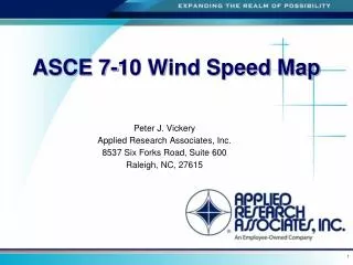
SS See ASCE 7-05 22 • Use Map to find the maximum considered ground motion for short periods. • The contours are irregularly spaced • Values are in % of g ASCE 7-05 Seismic Provisions - A Beginner's Guide to ASCE 7-05
S1 See ASCE 7-05 22 • Use Map to find the maximum considered ground motion for short periods. • The contours are irregularly spaced • Values are in % of g ASCE 7-05 Seismic Provisions - A Beginner's Guide to ASCE 7-05
Site Classes See ASCE 7-05 11.4.2, 20 • Site Classes are also labeled A-F • A is for hard rock, F for very soft soils • See definitions in ASCE 7-05 20 • Choice of site class is based on soil stiffness which is measured in different ways for different types of soil. • See ASCE 7-05 20 for procedure • If insufficient data is available, assume Site Class D unless there is a probability of a Site Class F. ASCE 7-05 Seismic Provisions - A Beginner's Guide to ASCE 7-05
Compute SMS and SM1 See ASCE 7-05 11.4.3 • SMS = FaSS • Fa from Table 11.4-1 • SM1= FvS1 • Fv from Table 11.4-2 ASCE 7-05 Seismic Provisions - A Beginner's Guide to ASCE 7-05
Spectral Response Accelerations SDS and SD1 See ASCE 7-05 11.4.4 • SDS is the design, 5% damped, spectral response acceleration for short periods. • SD1 is the design, 5% damped, spectral response acceleration at a period of 1 sec. • SDS and SD1 are used in selecting the Seismic Design Category and in the analysis methods. SDS = 2*SMS/3 SD1 = 2*SM1/3 ASCE 7-05 Seismic Provisions - A Beginner's Guide to ASCE 7-05
Design Response Spectrum See ASCE 7-05 11.4.5 • Period Limiting Values • T0 = .2 SD1/SDS • TS = SD1/SDS • TL from ASCE 7-05 22 • Sa, design spectral response acceleration • Sa is a function of structure period, T • Four regions, four equations. ASCE 7-05 Seismic Provisions - A Beginner's Guide to ASCE 7-05
Importance Factor, I See ASCE 7-05 11.5 • See ASCE 7-05 Table 11.5-1 • Function of Occupancy Category • Requirement for structures adjacent to occupancy category IV structures where access is needed to get to the category IV structure. ASCE 7-05 Seismic Provisions - A Beginner's Guide to ASCE 7-05
Seismic Design Categories See ASCE 7-05 11.6 • To be determined for every structure • function of: • Occupancy Category • Spectral Response Accelerations SDS and SD1. • Used to determine analysis options, detailed requirements, height limitations, and other limits on usage. • Seismic Design Categories labeled A-F ASCE 7-05 Seismic Provisions - A Beginner's Guide to ASCE 7-05
Seismic Design Categories • The most restrictive value controls • SDC E: • OC I, II, III where S1> 0.75 • SDC F: • OC IV where S1> 0.75 ASCE 7-05 Seismic Provisions - A Beginner's Guide to ASCE 7-05
Seismic Design Category A See ASCE 7-05 11.7 • Very limited seismic exposure and risk • Lateral forces taken to equal 1% of structure weight. • A complete load path must be in place. ASCE 7-05 Seismic Provisions - A Beginner's Guide to ASCE 7-05
Soil Report Requirements See ASCE 7-05 11.8 • Limits on where you can place a structure (SDC E or F) • SDC C – F: • specific evaluation of listed hazards. • SDC D-F: • Even more evaluation requirements. ASCE 7-05 Seismic Provisions - A Beginner's Guide to ASCE 7-05
Seismic Load Analysis Procedures See ASCE 7-05 12.6 • Equivalent Lateral Force (ELF) • Static approximation. • May not be used on structures of Seismic Design Categories E or F with particular irregularities. (ASCE 7-05 Table 12.6-1) • Modal Analysis • 2D and 3D dynamic analysis • Required for buildings with particular irregularities • Site Specific Response Spectrum • Permitted for all structures ASCE 7-05 Seismic Provisions - A Beginner's Guide to ASCE 7-05
Analysis Procedures • Category A: regular and irregular structures designed for a minimum lateral force • Category B & C: regular and irregular structures using any of the three methods • Category D, E, & F: Table 12.6-1 with some limits on SDS and SD1 • ELF for regular and some irregular • Modal for some irregular • Site specific required in Site Classes E or F ASCE 7-05 Seismic Provisions - A Beginner's Guide to ASCE 7-05
Structure Configuration(regular or irregular) • Plan Configuration • ASCE 7-05 12.3.2.1 • Vertical Configuration • ASCE 7-05 12.3.2.2 ASCE 7-05 Seismic Provisions - A Beginner's Guide to ASCE 7-05
Plan Structural Irregularities • 1a - Torsional Irregularity • 1b - Extreme Torsional Irregularity • 2 - Re-entrant Corners • 3 - Diaphragm Discontinuity • 4 - Out-of-plane Offsets • 5 - Nonparallel Systems ASCE 7-05 Seismic Provisions - A Beginner's Guide to ASCE 7-05
Type 1: Torsional Irregularities • 1a - Torsional Irregularity • larger story drift more than 1.2 times average story drift • 1b - Extreme Torsional Irregularity • larger story drift more than 1.4 times average story drift • Not permitted in Design Categories E & F • Design forces for lateral force connections to be increased 25% in Design Categories D, E, & F. ASCE 7-05 Seismic Provisions - A Beginner's Guide to ASCE 7-05
Type 2: Re-entrant Corners • Both projections beyond the corner are more than 15% of the plan dimension of the structure in the same direction ASCE 7-05 Seismic Provisions - A Beginner's Guide to ASCE 7-05
Type 3: Diaphragm Discontinuities • Diaphragms with abrupt discontinuities or variations in stiffness, including those having cutout or open areas greater than 50% of the gross enclosed diaphragm area, or changes in effective diaphragm stiffness of more than 50% from one story to the next. • Design forces for lateral force connections to be increased 25% in Design Categories D, E, & F. ASCE 7-05 Seismic Provisions - A Beginner's Guide to ASCE 7-05
Type 4: Out-of-Plane Offsets • Discontinuities in a lateral force resistance path, such as out-of-plane offsets of the vertical elements. • Design forces for lateral force connections to be increased 25% in Design Categories D, E, & F. ASCE 7-05 Seismic Provisions - A Beginner's Guide to ASCE 7-05
Type 5: Nonparallel Systems • The vertical lateral force-resisting elements are not parallel to or symmetric about the major orthogonal axes of the lateral force resisting system. • Analyze for forces applied in the direction that causes the most critical load effect for Design Categories C - F. ASCE 7-05 Seismic Provisions - A Beginner's Guide to ASCE 7-05
Vertical Irregularities • 1a - Stiffness Irregularity -Soft Story • 1b - Stiffness Irregularity - Extreme Soft Story • 2 - Weight (Mass) Irregularity • 3 - Vertical Geometry Irregularity • 4 - In-plane Discontinuity in Vertical Lateral Force Resisting Elements • 5 - Discontinuity in Capacity - Weak Story ASCE 7-05 Seismic Provisions - A Beginner's Guide to ASCE 7-05
Type 1: Stiffness Irregularities • 1a - Soft Story • the lateral stiffness is less than 70% of that in the story above or less than 80% of the average stiffness of the three stories above. • 1b - Extreme Soft Story • the lateral stiffness is less than 60% of that in the story above or less than 70% of the average stiffness of the three stories above. • Not permitted in Design Categories E & F ASCE 7-05 Seismic Provisions - A Beginner's Guide to ASCE 7-05
Type 2: Weight (Mass) Irregularity • Mass irregularity shall be considered to exist where the effective mass of any story is more than 150% of the effective mass of an adjacent story. A roof that is lighter than the floor below need not be considered. ASCE 7-05 Seismic Provisions - A Beginner's Guide to ASCE 7-05
Type 3: Vertical Geometry Irregularity • Vertical geometry irregularity shall be considered to exist where the horizontal dimension of the lateral force-resisting system in any story is more than 130% of that in an adjacent story. ASCE 7-05 Seismic Provisions - A Beginner's Guide to ASCE 7-05
Type 4: In-Plane Discontinuity in Vertical Lateral Force Resisting Elements • An in-plane offset of the lateral force-resisting elements greater than the length of those elements or a reduction in stiffness in the resisting element in the story below. • Design forces for lateral force connections to be increased 25% in Design Categories D, E, & F. ASCE 7-05 Seismic Provisions - A Beginner's Guide to ASCE 7-05
Type 5: Discontinuity in Capacity - Soft Story • A weak story is one in which the story lateral strength is less than 80% of that in the story above. The story strength is the total strength of all seismic-resisting elements sharing the story shear for the direction under consideration. • Do not confuse STIFFNESS with STRENGTH. • Not permitted in Design Categories E & F. ASCE 7-05 Seismic Provisions - A Beginner's Guide to ASCE 7-05
Equivalent Force Method(ASCE 7-05 12.8) ASCE 7-05 Seismic Provisions - A Beginner's Guide to ASCE 7-05
Base Shear Determination See ASCE 7-05 12.8.1 Base Shear, V = CsW Where: Cs = seismic response coefficient W = the effective seismic weight, including applicable portions of other storage and snow loads (See ASCE 7-05 12.7.2) ASCE 7-05 Seismic Provisions - A Beginner's Guide to ASCE 7-05
Seismic Weight, W See ASCE 7-05 12.7.2 • W is to include: • all dead load (all permanent components of the building, including permanent equipment) • 25% of any design storage floor live loads except for floor live load in public garages and open parking structures. • If partition loads are considered in floor design, at least 10 psf is to be included. • A portion of the snow load (20% pf minimum) in regions where the flat roof snow load exceeds 30 psf. ASCE 7-05 Seismic Provisions - A Beginner's Guide to ASCE 7-05