Download
1 / 21
240 likes | 594 Views
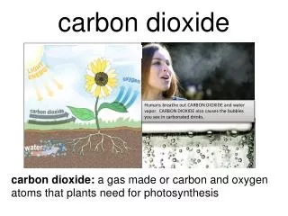
A Probabilistic Assessment Methodology for the Evaluation of Geologic Carbon Dioxide Storage. U.S. Geological Survey Department of the Interior. Outline for Briefing. Overview and Legislation Geologic Model Methodology Future Steps. Energy Independence and Security Act 2007.

E N D
A Probabilistic Assessment Methodology for the Evaluation of Geologic Carbon Dioxide Storage U.S. Geological Survey Department of the Interior
Outline for Briefing • Overview and Legislation • Geologic Model • Methodology • Future Steps
Energy Independence and Security Act 2007 • TITLE VII—CARBON CAPTURE AND SEQUESTRATION • Subtitle B—Carbon Capture and Sequestration Assessment and Framework • SEC. 711. CARBON DIOXIDE SEQUESTRATION CAPACITY ASSESSMENT. • (b) METHODOLOGY— …shall develop a methodology for conducting an assessment under subsection (f), taking into consideration— • (1) the geographical extent of all potential sequestration formations in all States; • (2) the capacity of the potential sequestration formations; • (3) the injectivity of the potential sequestration formations; • (4) an estimate of potential volumes of oil and gas recoverable by injection and sequestration of industrial carbon dioxide in potential sequestration formations; • (5) the risk associated with the potential sequestration formations; and • (6) the work done to develop the Carbon Sequestration Atlas of the United States and Canada that was completed by DOE. • (c) COORDINATION— • Federal Coordination • State Coordination
Source: DOE NETL, 2008, Carbon Sequestration Atlas II of the United States and Canada
How much needs to be sequestered? Some examples illustrate the range • World: ~ 8 Gt carbon/year or ~ 30 Gt CO2 /year • U.S. total all sectors in 2007 ~ 6 Gt/year CO2 (Energy Information Administration, 2009) • Laramie River 2&3 PC plant 1100 MWe 8.7 Mt/yr CO2 at 85% capacity factor (Brennan and Burruss, 2006) Millions of tons of CO2 EIA, Annual Energy Outlook
Carbon Capture and Storage • Capture: • Flue gas is 5 -15 % CO2, must be separated for storage • Compressed to a liquid for pipeline transport Original source: Statoil. Online at: http://ioc3.unesco.org/oanet/FAQocs.html • Geological storage: • The USGS assessment will focus on CO2 injected at depths of 3,000 to 13,000 ft • CO2 is buoyant and displaces existing water, oil, or gas • Storage formation must be sealed to retain buoyant CO2 • USGS assessment methodology addresses buoyant and residual trapping
USGS Methodology • Geologically-based, statistically-sound hypotheses for quantities of resource • Comprehensive & consistent treatment (compatible/comparable to assessments in other areas) • Transparent – methodology, assumptions • Probabilistic – range of values to reflect uncertainty • Not project site specific, estimates are regional (but geological models are developed for each region) • External expert input
To create a methodology for storage resources: • Define the geologic resource • Pore space accessible for storage (injection and retention) of CO2 • Define the geologic setting • Storage formation (net porous thickness) • Seal formation • Define the geologic model for the storage resource • Identify resource (trapping processes) • Buoyant Trapping (high storage efficiency) • Residual Trapping (low storage efficiency) • Use statistical method to estimate storage resource
Salinity of water in storage formation must be > 10,000 ppm TDS per EPA regulations
Basics of USGS CO2 Storage Formation Assessment Methodology • Estimate pore volume of Storage Formation • All pore space within Storage Formation is available for storage • Storage will be via either buoyant or residual trapping • Buoyant and residual trapping have very different storage efficiencies and risks
CO2 Trapping Types Buoyant Trapping Residual Trapping CO2 fills pore space, held in place by top and lateral seals CO2 droplets left behind by mobile plume, trapped by surface tension Beige = sand grains, Blue = water, Red = CO2
Buoyant Storage • The buoyant storage resource is based on petroleum reservoir-sized enclosures that will trap CO2 • To estimate the buoyant storage resource, we can use: • Petroleum production data to identify the known enclosures • USGS National Oil and Gas Assessment results to identify the undiscovered enclosures • Data gathered during CO2 assessment research to estimate the non-petroleum filled enclosures • Storage efficiency estimates: 10% min, 30% mode, 60% max (Bennion and Bachu, 2005, 2008; Burton and others, 2008 )
Residual Storage • The remainder of the pore space within the Storage Formation that is not available for buoyant storage is available for residual storage • The residual storage includes residual trapped CO2 and all buoyant trapping in enclosures that are less than petroleum reservoir-sized • The residual storage resource is divided into three classes based on variations in the permeability of the storage formation
Residual Storage Resource Classes • Class 1, High Permeability (> ~1 Darcy) • No injectivity problems • CO2 will flow easily and has the potential to bypass much of the residual trapping, which leads to lower storage efficiencies • Class 2, Medium Permeability (< ~1 Darcy, > ~1 millidarcy) • Little to no injectivity problems • Highest potential for residual trapping, due to lower flow rates • Class 3, Low Permeability (< ~1 millidarcy) • Significant injectivity problems • If CO2 can be injected, high residual trapping potential. But likely CO2 will not be injected into these rocks
Resource Triangle Technically accessible CO2 storage resources
To estimate CO2 storage resource we need to: • Develop a robust geologic model using the geologic properties of the Storage Formation • Estimate the pore volume of the Storage Formation • Determine the buoyant trapping pore volume • Determine the percentages of Class 1, 2, and 3 rocks within the Storage Formation. • Estimate buoyant and residual storage resources using a Monte Carlo simulator • Aggregate those storage resource values to estimate total storage within the Storage Formation
Implementation • The U.S. Geological Survey has started the assessment to estimate the CO2 storage resource of formations within sedimentary basins throughout the United States • The buoyant storage resource, the three classes of the residual storage resource, and the total aggregate storage resource of the Storage Formation, will be estimated for each suitable formation • The assessment will be completed within three years, resource estimates will be made available at that time • This assessment methodology will be used to assess the storage resource of the U.S., but it is applicable throughout the world
Conclusions • This method can estimate the technically accessible CO2 storage resource at a variety of levels of uncertainty across a formation • The methodology uses geologic data, processes, geologic models, and rock properties to populate probabilistic analysis models to produce a robust estimate of CO2 storage resource within a Storage Assessment Unit (SAU) • By calculating the buoyant storage resource separately from the residual storage resource, the user is provided with estimates that can be used to evaluate different scenarios
References Bennion, Brant, and Bachu, Stefan, 2005, Relative permeability characteristics for supercritical CO2 displacing water in a variety of potential sequestration zones in the Western Canada Sedimentary Basin, in Society of Petroleum Engineers Annual Technical Conference and Exhibition, 9–12 October 2005, Dallas, Tex., 2005, Proceedings: Richardson, Tex., Society of Petroleum Engineers, paper SPE 95547, 15 p., doi:10.2118/95547–MS [may require subscription to access]. Bennion, D.B., and Bachu, Stefan, 2008, Drainage and imbibition relative permeability relationships for supercritical CO2/brine and H2S/brine systems in intergranular sandstone, carbonate, shale, and anhydrite rocks: Society of Petroleum Engineers Reservoir Evaluation and Engineering, v. 11, no. 3, p. 487–496, doi:10.2118/99326–PA [may require subscription to access]. Burruss, R.C., Brennan, S.T., Freeman, P.A., Merrill, M.D., Ruppert, L.F., Becker, M.F., Herkelrath, W.N., Kharaka, Y.K., Neuzil, C.E., Swanson, S.M., Cook, T.A., Klett, T.R., Nelson, P.H., and Schenk, C.J., 2009, Development of a probabilistic assessment methodology for evaluation of carbon dioxide storage: U.S. Geological Survey Open-File Report 2009–1035, 81 p., available online only at http://pubs.usgs.gov/of/2009/1035/. Burton, McMillan, Kumar, Navanit, and Bryant, S.L., 2008, Time-dependent injectivity during CO2 storage in aquifers, in Symposium on Improved Oil Recovery, 20–23 April 2008, Tulsa, Okla., 2008, Proceedings: Richardson, Tex., Society of Petroleum Engineers, paper SPE 113937, 15 p., doi:10.2118/113937–MS [may require subscription to access]. Brennan, S.T., Burruss, R.C., Merrill, M.D., Freeman, P.A., and Ruppert, L.F., 2010, A probabilistic assessment methodology for the evaluation of geologic carbon dioxide storage: U.S. Geological Survey Open-File Report 2010–1127, 31 p., available only at http://pubs.usgs.gov/of/2010/1127. U.S. Department of Energy, National Energy Technology Laboratory, 2008, Carbon sequestration atlas of the United States and Canada (2d ed.; Atlas II): 142 p., accessed August 30, 2010, at http://www.netl.doe.gov/technologies/carbon_seq/refshelf/atlasII/atlasII.pdf. U.S. Energy Information Administration, 2010, Annual Energy Outlook 2010: 227 p., accessed August 30, 2010, at http://www.eia.doe.gov/oiaf/aeo/pdf/0383(2010).pdf.
For more information contact: Brenda Pierce bpierce@usgs.gov 703-648-6421 Peter Warwick pwarwick@usgs.gov Sean Brennan sbrennan@usgs.gov http://energy.usgs.gov http://energy.er.usgs.gov/health_environment/co2_sequestration/ http://pubs.usgs.gov/of/2010/1127/