Download
1 / 27
270 likes | 441 Views
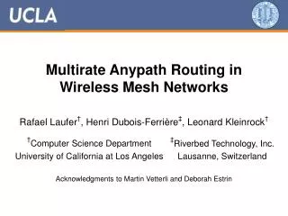
Orthogonal Rendezvous Routing Protocol for Wireless Mesh Networks. Bow-Nan Cheng Murat Yuksel Shivkumar Kalyanaraman. N. W. E. S. Motivation. ?. (4,6). D. By removing position information, can we still efficiently route packets?. S. D (X,Y) ?. (8,5). (15,5). (0,4). (12,3). (5,1).

E N D
Orthogonal Rendezvous Routing Protocol for Wireless Mesh Networks Bow-Nan Cheng Murat Yuksel Shivkumar Kalyanaraman
N W E S Motivation ? (4,6) D By removing position information, can we still efficiently route packets? S D(X,Y)? (8,5) (15,5) (0,4) (12,3) (5,1) Issues in Position-based Schemes
Motivation – Multi-directional Transmission Methods Multi-directional Antennas Tessellated FSO Transceivers 22.5o 45o Directional communications Model needed for ORRP
ORRP Introduction Assumptions • Neighbors are assigned a direction • Local Sense of Direction • Ability to Transmit/Receive Directionally • Directional, smart antennas • FSO transceivers A 98% Up to 69% B
ORRP Design Considerations • Considerations: • High probability of connectivity without position information[Reachability] • Scalability O(N3/2) total state information maintained. (O(N1/2) per node state information) • Even distribution of state information leading to no single point of failure [State Complexity] • Handles voids and sparse networks • Trade-offs • Path Stretch • Probabilistic Reachability
2 2 2 2 3 3 4 1 1 2 1 4 1 ORRP Proactive and Reactive Elements B C A • ORRP Announcements (Proactive) – • Generates Rendezvous node-to-destination paths D 2. ORRP Route REQuest (RREQ) Packets (Reactive) 3. ORRP Route REPly (RREP) Packets (Reactive) 4. Data path after route generation
Deviation Correction: Multiplier Angle Method (MAM) Concept Multiplier (m) E Interface Separation Angle 180o -90o=-2t Deviation Angle C t=45o 45o=1t Loop Prevention B D F A 180o 45o=1t G Desired Angle Received Angle New Multiplier (m) Actual Tx Angle
Multiplier Angle Method (MAM) Examples Basic Example VOID Navigation/Sparse Networks Example • = min(+4t, +4t) • = g + p - 4t m = +2 • = min(+4t, +4t) • = g + p - 4t m = +3 • = min(+4t, +6t) • = g + p - 4t m = +2 • = min(+4t, +6t) • = g + p - 4t m = +2 Void S R • = min(+4t, 0) • = g + p m = +3 • = min(+4t, 0) • = g + p m = 0
ORRP Void Navigation – differences from GPSR perimeter routing • ORRP seeks only intersections between destination ORRP packets and source ORRP packets – increased flexibility • MAM is an inherent nature of ORRP and not a special case that switches on and off like GPSR perimeter routing • ORRP does not require location-id mappings as GPSR does
Performance Evaluation of ORRP • Metric • Reachability – Percentage of nodes reachable by each node in network (Hypothesis: high reachability) • State Complexity – The total state information needed to be maintained in the network (Hypothesis: O(N3/2)) • Path Stretch – Average ORP Path vs. Shortest Path (Hypothesis: Low path stretch) • Analysis (without MAM) • Reachability Upper Bound • State Information Maintained at Each Node • Average Path Stretch • Packetized Simulation Scenarios Evaluated • Effect of MAM on reachability • Effect of finer-grained directionality • Total state complexity and distribution of state
2 1 3 Reachability Numerical Analysis P{unreachable} = P{intersections not in rectangle} Probability of Unreach highest at perimeters and corners NS2 Simulationswith MAMshow around99% reachability 4 Possible Intersection Points 57% 98.3% 99.75% 67.7%
ORRP Perimeter Issue • Perimeter/Corner Nodes – Corner nodes have higher probability of orthogonal line intersections outside of topology bounding region
Path Stretch Analysis • Average Stretch for various topologies • Square Topology – 1.255 • Circular Topology – 1.15 • 25 X 4 Rectangular – 3.24 • Expected Stretch – 1.125 x = 1.255 x = 1.15 x = 3.24
State Complexity Analysis/Simulations ORRP state scales with Order N3/2 ORRP states are distributed fairly evenly (no single pt of failure)
Reachability – Finer Grained Directionality (NS2 Simulations) • Observations/Discussions • For sparse networks, reachability increases dramatically as number of interfaces increases. This is due to more node choices to effectively route paths • Non-complete reachability even with MAM due to network “fingers” Finer-grained interface spread have increased effectiveness in sparse networks to a point Finer-grained interface spread increases reach in networks with voids
Additional Results (in brief) • MAM increases reachability to almost 100% even in rectangular topologies in NS2 simulations • Path stretch with MAM stays relatively constant even with finer granularity of antenna spread (discounting unreach) • Numerical Simulation of “additional lines” yields very littleREACH and PATH STRETCH gain while adding a lot of additional state
Summary • ORRP achieves high reachability in random topologies • ORRP achieves O(N3/2) state maintenance – scalable even with flat, unstructured routing • ORRP achieves low path stretch (Tradeoff for connectivity under relaxed information is very small!)
Future Work • Mobile ORRP (MORRP) • Hybrid Direction and Omni-directional nodes • More detailed abstraction to 3-D • Route loop prevention • ORRP for peer to peer networks requires the concept of locally consistent virtual direction Thanks! Questions or Comments: chengb@rpi.edu
Affect of Control Packet TTL on Varying Network Densities (NS2) • Observations/Discussions • Reachability increases heavily when TTL is increased from 2 to 7 but stays roughly constantly with continued increases (Saturation Pt.) • Total States increases dramatically from setting a TTL of 2 to 7 and then stays constant • Average path length remains unchanged with TTL Reach increases until SaturationPt with increase in TTL Total States increases until SaturationPt with increase in TTL Average Path Length Remains constant with varying TTL
Additional Lines Study • Observations / Discussions • Probability of reach is not increased dramatically with addition of lines above “2” • Path stretch is decreased with addition of lines but not as dramatically as between “1” and “2” • Total States maintained is increased heavily with increase in number of lines
Free-Space-Optical Ad Hoc Networks Motivation – Hybrid FSO/RF MANETs • Current RF-based Ad Hoc Networks: • 802.1x with omni-directional RF antennas • High-power – typically the most power consuming parts of laptops • Low bandwidth – typically the bottleneck link in the chain • Error-prone, high losses Free-Space-Optical (FSO) Communications Mobile Ad Hoc Networking • High bandwidth • Low power • Directional – secure, • more effective use of medium • Mobile communication • Auto-configuration • Spatial reuse and angular diversity in nodes • Low power and secure • Electronic auto-alignment • Optical auto-configuration (switching, routing) • Interdisciplinary, cross-layer design
State Complexity – Varying Number of Interfaces (NS2 Simulations) • Observations/Discussions • Total States increases with the number of nodes in the network (expected) • Total states is not very dependent on the number of interfaces • Increase in Total States maintained consistent with increased reachability (more states = more reachability)
Stretch – Average Path Length vs. Varying Interfaces (NS2 Simulations) • Observations/Discussions • As node density increases, path length increases as next hop nodes are chosen at random from the nodes within the transmission range + LOS. With more nodes, there is more choices of “closer nodes” • Average Path Length improves for dense networks with more interfaces. More interfaces increases granularity and limits node selection
ORRP Introduction Assumptions • Neighbor Discovery • 1-hop neighbors • Given direction/interface to send packets to reach each neighbor • Local Sense of Direction • Ability to Transmit/Receive Directionally • Directional, smart antennas • FSO transceivers
Deviation Correction: Multiplier Angle Method (MAM) • Important Notes: • Only corrections outside of antenna spread considered • MAM assumes that relative distances from one hop to another are relatively equal • All deviation correction done at RREQ and ORRP Announcement level (not on each transmission)
ORRP Packet Deviation Issue • Sending in orthogonal directions increases likelihood of intersections(Single line: 69% intersection vs. Orthogonal Lines: 98% intersection) • Packet deviation potentially lowers the likelihood of intersections(ie: if packets end up traveling in parallel paths) • Question: How can we maintain straight paths as much as possible without adding too much overhead to the system?
Thanks! Can directionality be used at Layer 3? YES!