Download
1 / 64
640 likes | 789 Views
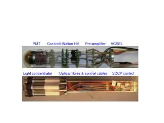
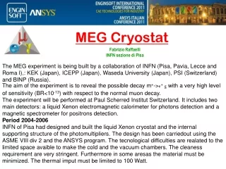
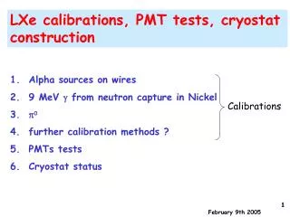
Calibrations. LXe calibrations, PMT tests, cryostat construction. Alpha sources on wires 9 MeV from neutron capture in Nickel 0 further calibration methods ? PMTs tests Cryostat status. Sorces at different distances seen by each PMT : unique feature Made at Genova INFN

E N D
Calibrations LXe calibrations, PMT tests, cryostat construction • Alpha sources on wires • 9 MeV from neutron capture in Nickel • 0 • further calibration methods ? • PMTs tests • Cryostat status
Sorces at different distances seen by each PMT: unique feature Made at Genova INFN electrodeposited ( solution) on a gold-plated W wire 0.5 mm spots 12.4 cm apart (2 PMTs) Wire thickness: 50 (alpha range ~40 ) Wire suspended with springs Wires A,B = 100 Bq/source (LP front face) Wires C,D = 30 Bq/source (LP back face) A Czech Republic firm can provide a suitable wire in which Am on foils is attached to wires by thermocompression 1) Alpha sources spots on wires LP Front face Lateral face
The ring radius depends on the Rauleigh scattering length • The best value for reproducing the radius is 20 cm • In contrast with previous estimates! • Reflection ? ...we must improve the simulation and detector understanding
Charge vs Cos in LXe Front Face Data MC
LXe/MC New PMTs 4 front sources Old PMTs
LXe/MC 4 front sources After applying QEs
Towards the final calorimeter 70 kHz photons with E>5 MeV from muon radiative decay @ R() 3x10**7. Total sources rate O(15 KBq @ 5 MeV)
Trigger was changed several times … Po half-life=138 days
AMERICIUM WIRE-SOURCES • World-wide search (from 2003...): • ISOTRAK-AEA TECHNOLOGY • ISOTOPE PRODUCTS • LEA-CERCA • NORTH AMERICAN SCIENTIFIC • FRAMATOME • ETC. • all of them refused to consider this custom-made product....! • too difficult, too long development, too expensive, etc. Finally:found a factory,Czech republic, Prague working on ionization smoke detectors and electrostatic charge eliminators (8 people.....) accepted to perform a R&D for our special request. UP and DOWN SUCCESS !: Production method by “thermocompression”. Liquid Nitrogen tests at ENEA. VERY IMPORTANT FOR FUTURE CRYOGENIC LIQUID DETECTORS unique feature !
SPECITICATIONS AND CONTRACT FOR THE PRODUCTION OF Am WIRE-SOURCES AND OF Am DISK-SOURCES Ready: end of March 2005 (TOTAL ACTIVITY < 40 kBq) Each dot-source: small radioative foil fixed on wire by “thermocompression” TESTED AT NITROGEN TEMPERATURE AT THE ENEA LAB. IN ROME. OK ! • NEEDED FROM PSI: • Authorization of nuclear security • for products • Authorization for import of • radioactive sources • Auhorization for production of • detectors using radioactive sources
WIRE SOURCES FOR FINAL CALORIMETER 15 WIRES, 5 DOT-SOURCES PER WIRE 150 cm total wire length 12.4 cm distance between Am dots Central Dot 20.0 cm distance between Mark and First Dot Am dots Reference Mark Wire of 100 micron diameter Material: gold plated steel or tungsten Total length 150 cm Spacing of dot-sources 12.4 cm Linear dimension of dots 1-2 mm Activity 200Bq per dot
WIRE SOURCES FOR LARGE PROTOTYPE 10 WIRES, 2 DOT-SOURCES PER WIRE 150 cm total wire length 12.4 cm distance between Am dots Wire centre 20.0 cm distance between Mark and First Dot Am dots Reference Mark Wire of 100 micron diameter Material: gold plated steel or tungsten Total length 150 cm Spacing of dot-sources 12.4 cm Linear dimension of dots 1-2 mm Activity 200Bq per dot
WIRE SOURCES FOR PISA DEVICE 2 WIRES, 1 DOT-SOURCE PER WIRE 50 cm total wire length Reference Mark Central Am Dot 20.0 cm distance between Mark and Dot Wire of 100 micron diameter Material: gold plated steel or tungsten Total length 50 cm Central dot-source Linear dimension of dots 1-2 mm Dot Activity 200Bq
rather narrow energy-spectra possible mounting on special supports and screws
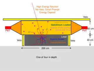
2) 9 MeV gamma line from neutron capture on Nickel:Experimental set-up • Am-Be source • (20000 n/s); • Polyethylene; • Nickel plates • 30 x 30 cm2 • (0.5 cm and 0.25 cm • thickness) • 20 x 20 x 36 cm3 • NaI detector • MCAORTEC • (2048 channels) • NIM electronics.
γ-line from n-capture on Ni, I, Al, H2; natural radioactivity Tl, K; Am/Be source K 1.46 MeV H2 2.2 MeV Am/Be 4.4 MeV & 1st escape Ni 8.54 MeV & 1st escape Tl 2.6 MeV I 6.8 Mev Ni 9 MeV Al 7.7 MeV Black: Am/Be source and 1 cm Ni Red: no Am/Be source Green: no Am-Be source, no Ni (Gotta Beam on)
neutron generator (Pavia ?) 20 cm 3 cm THERMAL NEUTRON CAPTURE ON NICKEL D + 2H 3He + n Q = 3.27 MeV D + 3H 4He + n Q = 17.59 MeV • Potentialities : • switchable on-off • frequent (s, m,...) stability checks • system out of the calorimeter • Ni and Xe, prompt and delayed signals • probably: visible signal at full beam intensity • time reference 9 MeV Nickelγ-line • Open problems: • monitoring from calorimeter back • only at one location ? • some dispersed neutrons and radioactivity • test of the method at high beam intensity • useful test with the “large prototype” • (already foreseen in April, with Am/Be source) NaI 20 x 20 x 36 cm3 • Intensities from 106 n/s to 108 n/s • Typical pulse rate and pulse width 10 Hz and 1 μs • Time separation of direct from delayed reactions • Single pulse mode Polyethylene 0.25 cm Nickel plate
Possibilities POLY POLY POLY POLY POLY NaI n Am/Be 0.25 cm Nickel 3 cm polyethylene
How often can it be performed? 3) p0calibration… Anti Counter Support structure: straightly up and down Tilt mechanism at every height for NaI front to face target direction. tilt • Proton beam: 1.8mA • Pion Rate: 2x10⁷p-/sec • Collimate: 2PMTs x 2PMTs ~ 150cm2 • (1 position) • 2 g/sec • # of PMTs on incident face: 216 PMTs (54 positions) • required: 30,000 evts/position • takes 30,000 x 54 / 2 = • 810,000sec~ 10 days g Target up p0 down g target
3) Further calibration methods... 500 KV PROTON ACCELERATOAND LITIUM TARGET FOR A 17.6 MEV GAMMA LINE 37Li (p,)48Be [P.R. 73, 666 (1948), N.P. 21 1 (1960), Zeitschrift f. Physik A351 229 (1995)] • Potentialities : • a unique nuclear reaction with a high energy -line (10 KeV) • obtainable : 106 /s (isotropic) at 440 KeV resonance (Ip 50 A) • from LiF target at COBRA center; ’s on the whole cal. entrance face • energy and position calibration; shower properties; all over LXe cal. • possibly: rather frequent use • Open problems: • compatibility with normal beam and target ? • project for easiness of target-tube mounting • accelerator/COBRA, which position and distance ? • p-beam divergence and protons on target; p29 MeV/c • 500 KeV and criticality of an air-insulated accelerator • is a post-acceleration possible ?
37Li (p,)48Be resonant at Ep= 440 keV =14 keV peak = 5 mb E0 = 17.6 MeV E1 = 14.6 6.1 Bpeak 0/(0+ 1)= 0.720.07 NaI 12”x12” spectrum Crystal Ball Data 0 1
Cecil et al. NP A539 75 (1992) 10x10 cm NaI crystal A further interesting possibility... 511B (p,)612C resonant at Ep= 163 keV = 7 keV E0 = 16.1 MeV peak = 5.5 b E1 = 11.7 + 4.4 peak = 152 b • 7500/s (isotropic) • 20.0001/s for Ip 50 A lower proton energy ! lower rate at 50 A !!
NOW: GLAST SPACE EXPERIMENT CRYSTAL CALORIMETER CALIBRATION 180 cm target-pipe It is the old VDG of the Crystal Box experiment ! ! they have some problems: old device, max. VDG p-energy is 400 KeV out of resonance: -rate reduced by factor 5000 How can we get one such device ?? We are exploring several possibilities...
Cal. calibration from the target position,monitoring at the cal. back rails cockroft focusing elements (magnetic or electrostatic ?) at the cal. back the proton motion in the COBRA field must be be studied
proton MC trajectoriesEp 440 keV 28 MeV/c!! Y(cm) the protons are not reflected back by the varying magnetic field Θ ~ 8 giroradius < 12 cm X(cm) Z(cm)
Plane Z = 0 cm Y(cm) ρ ~0.8cm X(cm) Θ ~ 0.5 giroradius < 1 cm Z(cm)
KEEP MEG UNDER CONTROL PARTICULARLY AT HIGH (AND VARIABLE) BEAM INTENSITIES......... BR eg~10-13 Beam Intensity~5 107 /s • frequent checks of calorimeter energy scale, linearity and stability • checks of LXe optical properties • energy resolution and spacial resolution • shower properties • at the right energy ( 53 MeV), but also at other energies..... no single calibration method has all the required characteristics use complementary (and redundant) methods, make the best use of their intrinsic properties emphasize the reliability of our experiment
5) PMT tests PMT in LP, LED pulsed (@ 1 khz) F18, TB type F0, 6041 (old) <Q>= 50 pC <Q>= 87 pC
10 Khz TB 6041 <Q>= 50 pC <Q>= 87 pC photocathode saturation effect
50 Khz 6041 TB <Q>= 50 pC <Q>= 87 pC photocathode saturation effect
100 Khz 6041 TB <Q>= 50 pC <Q>= 87 pC Gain non linearity
6041 t = 115 s Anode current should be < 0.5 mA
TB Lower photocathode resistivity (ZA much better)
Linearity much improved presently installed T=-108ºC PMT with Zener
Positive pulses with total positive charge are seen! (rate ~300 Hz @ V>20 mV) The problem is present ONLY at liquid Xe temperature: disappears during warm-up The pulse is not present when the Zener diodes are removed But … Zener problem at low temperature
R9288 base with low pass filter • Low pass filter is built in • by adding resistors serial to Zener • If the resistance is too small, filtering will not work. • With too large resistance, the effect of Zener will be little • under high rate BG environment Optimum resistance will be something around 100KOhm
PMT base with Zener diode and low pass filter is adopted in Astro-E2 Hard X-ray Detector. (HXD) Fifth Japanese space X-ray observatory PMT+BGO High counting rate HXD will be cooled downed to –30 °C Low pass filter in PMT base @ Astro-E2 HXD Zener is used in this base circuit and low pass filter is built in because of the noise from Zener. Various tests have been performed with this base and its good performance was confirmed so far.
PMT Test using the base with Low Pass filter Type Z Type ZR
Type Z Chamber Set Up Upper PMT temp. ~ - 85 °C HV=800V for both PMTs Same interstage volt., same current between 2 PMTs Alpha source LED Type ZR Gas xenon Lower PMT temp. ~ - 100 °C
Oscilloscope Snapshot Noise from Zener Type Z No noise was observed!! Alpha event Type ZR Yasuko HISAMATSU MEG Collaboration Meeting Feb. 2005