Manual Transmissions
490 likes | 965 Views
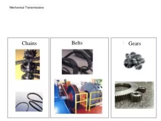
Manual Transmissions. Sliding Gear Transmission Old school, used from late 1800’s to 1940’s? Has two or more shafts in parallel with sliding spur gears. Sliding Gear Transmission If either gear is rotating, shifting is difficult and gear “clashing” will result.

Manual Transmissions
E N D
Presentation Transcript
Sliding Gear Transmission • Old school, used from late 1800’s to 1940’s? • Has two or more shafts in parallel with sliding spur gears.
Sliding Gear Transmission • If either gear is rotating, shifting is difficult and gear “clashing” will result. • Some manufacturers may still have a sliding gear for reverse.
Collar-shift Transmission • Has two parallel shafts with gears in constant mesh • These “collars” slide on a hub that is splined to the output shaft, thus transferring power. • Gear “clashing” will occur if the gear speeds are not matched by double clutching.
Double Clutching • The shifter, rather than going straight to the next gear, makes a stop in neutral and then the clutch is released. • This is to allow the engine to slow down (or with a tap on the gas, speed up when downshifting) so the transition into the next gear is much more smooth. • The driver then depresses the clutch again and completes the shift into the target gear, and finally the clutch is released again, putting the car back into gear.
Synchromesh Transmissions • Gears are in constant mesh and are collar shifted • All forward gears are of a helical design
Synchromesh Transmissions • Collars are equipped with synchronizers • Synchronizers eliminate the need to equalize gear speeds before engagement • Used on all current models of cars – may use a spur gear for reverse
Synchromesh Transmissions • Engine torque is applied to the input shaft (clutch shaft) when the clutch is engaged. • The input shaft is fitted with a gear (input gear or clutch gear) • The output shaft (main shaft) is inserted into, but rotates independently of the input shaft.
Synchromesh Transmissions The different speed gears (1st, 2nd, 3rd 4th, etc.) rotate on the main shaft.
Synchromesh Transmissions • Parallel to (below or beside) the input and output main shaft is the counter shaft • The counter shaft is fitted with different sized gears.
Synchromesh Transmissions • All of these gears are in constant mesh with the gears on the output shaft except … • One gear is in constant mesh with the input shaft gear.
Synchromesh Transmissions • Gear changes occur when the selected gear is connected to the output shaft. • This is accomplished by locking a collar onto the selected gear. • The collars are moved by shift forks.
Synchromesh Transmission Switch to ppt #2
Transmission Components Input Shaft
Synchronizer Operation • First, the sleeve is moved toward the gear by the shift lever and engages the hub assembly • Second, the movement of the sleeve causes the inserts to press the blocking ring onto the cone of the gear
Synchronizer Operation • Third, when the components reach the same speed, the synchronizer sleeve slides over external dog teeth on the blocking ring and over the dog teeth of the speed gear’s shoulder. This action locks the gear to the main shaft.
Transmission Operation • Power flow in neutral • The input shaft drives the counter shaft • All of the gears on main shaft rotate • The synchronizers are not engaged with any gear • No power is transferred to the output shaft
Power flow in first gear • The power enters the transmission through the input shaft • The first/second synchronizer sleeve is engaged with the first gear dog teeth • The power is transferred from the input shaft, through the countershaft, and up to the first gear • The first gear drives the output shaft
Power flow in second gear • The power enters the transmission through the input shaft • The first/second synchronizer sleeve is engaged with the secondgear dog teeth • The power is transferred from the input shaft, through the countershaft, and up to the second gear • The secondgear drives the output shaft
Power flow in third gear • The power enters the transmission through the input shaft • The third/fourth synchronizer sleeve is engaged with the third gear dog teeth • The power is transferred from the input shaft, through the countershaft, and up to the thirdgear • The thirdgear drives the output shaft
Power flow in fourth gear • The power enters the transmission through the input shaft • The third/fourth synchronizer sleeve is engaged with the fourth gear dog teeth • The power is transferred from the input shaft to the fourth gear • The fourthgear drives the output shaft
Power flow in fifth gear • The power enters the transmission through the input shaft • The fifth gear synchronizer sleeve is engaged with the fifth gear dog teeth • The power is transferred from the input shaft, through the countershaft, and up to the fifth gear • The fifth gear drives the output shaft in overdrive
Power flow in reverse gear Reverse is often achieved by adding a third gear -causing the output shaft to spin in the opposite (same) direction
Power flow in reverse gear • The power enters the transmission through the input shaft • The reverse gear synchronizer sleeve is engaged with the reverse gear dog teeth • The power is transferred from the input shaft, through the countershaft, through the reverse idler gear, and up to the reverse gear • The reverse gear drives the output shaft in reverse
GEAR RATIO FINAL • 1st 2.66:1 9.10:1 • 2nd 1.78:1 6.10:1 • 3rd 1.30:1 4.45:1 • 4th 1.00:1 3.42:1 • 5th 0.74:1 2.53:1
Transaxle A manual trans-axle is almost identical to a manual transmission except: 1. The differential is built into the housing 2. The input shaft incorporates gears 1,2,3 @4 2. The counter-shaft is now the output shaft 3. The gears are generally smaller and pressed fit to facilitate a smaller area.
Transaxle Input and output shafts
Transaxle First Gear
Transaxle Fourth Gear
Transaxle Reverse
Fluids … are used to _ ? _ ? …check the manufacturers specifications!