CesrTA E-cloud Activities (Jan. 2009)
290 likes | 432 Views
CesrTA E-cloud Activities (Jan. 2009). J.W. Flanagan, KEK. Organization. CesrTA meeting slides from 2009.2.11 WebEx, provided by Mark Palmer Have tried to attribute original authors correctly. Supplemental slides on some contributions from KEK. M. Palmer (CesrTA Mtg.).

CesrTA E-cloud Activities (Jan. 2009)
E N D
Presentation Transcript
CesrTAE-cloud Activities(Jan. 2009) J.W. Flanagan, KEK
Organization • CesrTA meeting slides from 2009.2.11 WebEx, provided by Mark Palmer • Have tried to attribute original authors correctly. • Supplemental slides on some contributions from KEK
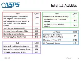
M. Palmer (CesrTA Mtg.) CesrTA Run & Down Recap • Completed experimental run 2/2/2009 • Low emittance correction in 2.085 GeV baseline optics • X-ray Beam Size Monitor (xBSM) commissioning • EC Measurements • RFA & TE wave measurements • Dynamics • General instrumentation/feedback tests/commissioning • 13 visitors • LET - J. Jones, A. Wolski • xBSM – J. Flanagan, H. Sakai • EC – S. De Santis, R. Holtzapple, K. Shibata, L. Wang • Feedback – D. Teytelman, M. Tobiyama • CLIC – H. Schmickler • Instrumentation – A. DellaPenna, I. Pinayev • 2nd upgrade down is underway… • Installation of PEP-II experimental hardware • Installation of photon stop chamber for 5GeV operation of the CesrTA L0 wiggler straight • Replacement of SRF cavity that failed during summer 2008 • Installation of xBSM beam line front end for electron beam • Continue with instrumentation upgrade for 4ns bunch train operation • Contingency item: Repair of 15BW dipole coils CesrTA-KEK Update
D. Rubin (CesrTA Mtg) Optics and LET • Low emittance 2.085 GeV optics loaded and corrected • Correction methods tested • Beam-based alignment measurements • Coupling and dispersion bumps created for tuning • Emittance measurements begun… • Touschek lifetime measurements initially used to characterize beam size • xBSM measurements as detector and optics were characterized • Ongoing program of magnet alignment to improve emittance • Alignment work continued throughout the run • 2 anomalous locations in the ring have been identified which are being scrutinized. CesrTA-KEK Update
First Detailed Optics Correction a Touschek Study a xBSM Measurement (Preliminary) A. Wolski (CesrTA Mtg.) Wolski Measured energy acceptance = 0.7% v ~ 32pm From xBSM v ~ 155 m v ~ 38pm Appear to be within a factor of 2 of the 20pm target CesrTA-KEK Update
J. Alexander (CesrTA Mtg.) xBSM Snapshots (Preliminary) Fresnel Zone Plate • Scan of coupling knob • Coded aperture measurements • Smallest recorded size: ~15 mm (but further calibration work needed) Simulations Coded Aperture Measurement <20mm beam size CesrTA-KEK Update
G. Dougan(CesrTA Mtg.) EC Data-Simulation Updates • Simulations of tune shifts in POSINST at Cornell and LBNL, using a new option in POSINST for offseting the bunches, have shown that the tune shifts of a single bunch are different if the whole train is oscillating coherently, than if just the single bunch is oscillating. • Horizontal tune shifts in a dipole are much smaller when the whole train is oscillating coherently. This is particularly relevant for the tune shift measurements at CesrTA, since we kick the whole train coherently to do the measurement. • Tune shifts calculated for a coherently oscillating beam give better agreement with measurements: see following three slides. • January run • Studies of systematic effects in the tune shift measurements were carried out. • Measurements of tune shift vs. current for long trains (10, 20, 45 and 116 and 145 bunches) were carried out (evidence of instability developing at the end of the 116 and 145 bunch trains) • RFA and TE wave measurements to characterize EC density in drifts, dipoles and wigglers • Work on comparisons between RFA and TE wave measurements as well as systematics checks for both CesrTA-KEK Update
10 Bunch Train with Trailing Witness Bunch(es) Data-POSINST Comparison (Preliminary) G. Dougan(CesrTA Mtg.) Positron Beam Blue a Vertical DQ Red a Horizontal DQ Squares a Simulation Circles a Data CesrTA-KEK Update
10 Bunch Train with Trailing Witness Bunch(es) Data-POSINST Comparison (Preliminary) G. Dougan (CesrTA Mtg.) Electron Beam Blue a Vertical DQ Red a Horizontal DQ Squares a Simulation Circles a Data CesrTA-KEK Update
G. Dougan (CesrTA Mtg.) Drift vs Dipole Contributions • Comparison of drift (red) and dipole (blue) contributions to tune shifts in each dimension Vertical Horizontal CesrTA-KEK Update
45 Bunch Train: Data-POSINST Comparison (Preliminary) G. Dougan (CesrTA Mtg.) Positron Beam Blue a Vertical DQ Red a Horizontal DQ Squares a Simulation Circles a Data CesrTA-KEK Update
G. Dougan (CesrTA Mtg.) L0 RFA Data 2E Segmented RFA Wiggler with RFAs and TiN-coated VC e+ e- Wiggler with RFAs and uncoated Cu VC 2/3/08 2W Segmented RFA CesrTA-KEK Update
Electron-Positron Comparisons (1x45 Current Scans) G. Dougan (CesrTA Mtg.) Segmented drift Cu wiggler (pole center) 2W detector downstream of wigglers for e+ beam fPositronsg Segmented drift 2E detector downstream of wigglers for e- beam Cu wiggler (pole center) fElectronsg CesrTA-KEK Update
G. Dougan (CesrTA Mtg.) Long Train Data Dipole (Al VC) • 1x145 e+ • 14 ns spacing a 79% of ring filled • Multipacting stripe • Strongly visible in dipole • Weaker in L0 wiggler and drift regions Cu wiggler, pole center Drift (Cu VC) CesrTA-KEK Update
M. Palmer (CesrTA Mtg.) Segmented RFA Shielded Pickups 15E/W test chamber design for coating tests Plans • CESR layout modifications to be completed by March 1 • 4 Experimental areas for EC build-up and mitigation studies • L0 wiggler straight • Configured for RFA and TE Wave measurements of EC build-up • 4 wiggler comparisons planned (CU-KEK-LBNL-SLAC collab.) • Cu vacuum chamber (installed) • TiN coated vacuum chamber (installed) • Grooved vacuum chamber (a summer ’09 installation) • Clearing electrode vacuum chamber (a fall ’09 installation) • L3 straight w/PEP-II chicane and SEY sample station • Sample station tests (CU-FNAL-SLAC collab.) • Grooved chamber tests (CU-SLAC collab.) • 15E/W • Flexible location for testing chambers with dipole synchrotron radiation • Presently planned comparisons (summer/fall ’09) • Al vacuum chamber • a carbon coated VC (CERN-CU collab.) • Enamel chamber with electrode (Project X collab.) • TiN-coated Al vacuum chamber • Detailed beam dynamics studies at ultra low emittance • Mid-2009 a end of program • Characterize instability thresholds • High resolution bunch-by-bunch beam size measurements to characterize incoherent emittance growth • Witness bunch studies for flexible control of EC interaction with beam CesrTA-KEK Update
KEK Participation in CesrTA • Several members of KEKB are participating in CesrTA: • K. Ohmi (electron cloud instability dynamics studies and simulation) • M. Tobiyama (instrumentation and feedback) • K. Kanazawa, Y. Suetsugu, K. Shibata (vacuum group: electron cloud mitigation measures) • J. Flanagan (e-cloud studies and diagnostics, x-ray beam size monitor) • +H. Fukuma, N. Ohuchi, … • Note: Funding provided by US-Japan Cooperation Program (Nichibei) • ATF members also participating: • H. Sakai (U. Tokyo): X-ray beam size monitor • K. Kubo: Low emittance tuning • Reverse direction (from Cornell): • Jim Alexander -> KEK for x-ray monitor readout tests • Jim Shanks -> ATF for low emittance tuning • Others likely not listed
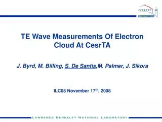
Bunch-by-bunch Feedback • Longitudinal feedback at 4 ns successfully demonstrated in January 2009 by Dmitry Teytelman (Dimtel, formerly SLAC) using iGp • iGp: Next generation digital feedback system developed by collaboration of SLAC (J. Fox, D. Teytelman), KEK (M. Tobiyama), INFN (A. Drago), Dimtel • Transverse feedback also demonstrated.
Mitigation methods:PRELIMINARY results from KEKB • Techniques also being tested at CesrTA • Clearing Electrode (Suetsugu, Fukuma et al. design) • Design being worked on for CesrTA • Grooved Chamber (Pivi et al. design) • Being installed at CesrTA for testing in summer run
K. Shibata (KEKB Review) Clearing Electrode 1 Study on clearing electrode also started for mitigation of electron cloud in magnets. Very thin electrode (0.1 mm, Tungsten) and insulator (0.2 mm, Al2O3) were developed. (Thermal Spray) Clearing electrode and electron detector were installed in wiggler magnet of LER. (placed at the center of pole) To demonstrate the effect of electrode, the electron density was measured by the electron detector with 7 strips. 7 strips can measure the horizontal spatial distribution of the electron cloud. Y. Suetsugu et al., NIM-PR-A, 598 (2008) 372 Sustainability for high beam current was also tested. Tungsten Al2O3 40 mm Feed-through 440 mm Stainless steel The 14th KEKB Review on 9-11 February 2009 at KEK
K. Shibata (KEKB Review) Clearing Electrode 2 Electron detector Collector (7 strips, w5 mm) Cross-section Grid (~ 1 kV) Shield Monitor Block f2 mm holes R47 Beam Clearing electrode Electrode [W] (~ +1 kV) Cooling channel (w40, l440, t~0.1) Test chamber Insulator [Al2O3] (t~0.2 mm) Electrode Block Limited by magnet aperture Vacuum seal by metal O-ring Cooling Water paths Wiggler magnet Magnetic filed : 0.77 T Effective length : 346 mm Aperture (height) : 110 mm Y. Suetsugu et al., NIM-PR-A, 598 (2008) 372 The 14th KEKB Review on 9-11 February 2009 at KEK
K. Shibata (KEKB Review) Clearing Electrode 3 Drastic decrease in electron density was demonstrated by applying positive voltage. Number of electrons was reduced to 1/10 1/100if applied voltage of clearing electrode was more than 300 V for any bunch spacing. Vr = 1.0 kV B = 0.77 T Y. Suetsugu et al., NIM-PR-A, 598 (2008) 372 1585 bunches (Bs ~ 6 ns) ~1600 mA Collector : #4 [6ns] negative Velec = 0 Ie [A] [4ns] Velec [V] [16ns] 1 x 10⁻⁵ 1 x 10⁻⁶ [8ns] Ie [A] 1 x 10⁻⁷ 1 x 10⁻⁸ positive 1 x 10⁻⁹ Velec [V] Collectors The 14th KEKB Review on 9-11 February 2009 at KEK
K. Shibata (KEKB Review) Clearing Electrode 5 Electrode was very effective, but modification of the feed-through connection part is required for high beam current. Insulation resistivity decreased from 2 M to several 10 k during the trial period due to discharge at feed-through connection part. Improved clearing electrode will be installed this winter. insulator electrode Y. Suetsugu Connection part The 14th KEKB Review on 9-11 February 2009 at KEK
K. Shibata (KEKB Review) Groove Surface 1 Effect of groove surface was also studied last autumn. (collaboration with SLAC) Flat surface [SUS + TiN] Electrode was replaced by groove surface. Same setup for clearing electrode was utilized. Groove structure was designed and manufactured in SLAC. Flat surface with TiN coating was also tested for reference. TiN~200 nm Y. Suetsugu, ILCDR2008 TiN~200 nm [Groove] R47 Magnetic field Beam [Monitor] Groove surface [SUS + TiN] The 14th KEKB Review on 9-11 February 2009 at KEK
K. Shibata (KEKB Review) Groove Surface 2 Electrons for groove surface was reduced to 1/5 1/10the number for flat surface (3 buckets spacing). Further R&D will be carried out toward the practical use of groove surface. Groovesurface Flatsurface Y. Suetsugu 1x10⁻⁶ 1x10⁻⁶ Preliminary result The 14th KEKB Review on 9-11 February 2009 at KEK
K. Shibata (KEKB Review) Mitigation Performance Comparison Clearing electrode is much more effective than groove surface and TiN coating. Vr = -1 kV (1/1585/3.06) ~1x10¹² e-/m3 Preliminary result ~1x10¹¹ ~1x10¹⁰ ~1x10⁹ Ranking of estimated performance in magnet is ; Electrode>> TiN+Groove >>TiN(Flat) >Cu(Flat) 10 51023 Electrode and groove surface are very promising, but more studies are required to achieve the practical use of them. The 14th KEKB Review on 9-11 February 2009 at KEK
X-ray monitor: Coded Aperture Imaging •Technique developed by x-ray astronomers using a mask to modulate incoming light. •Resulting image must be de-convolved through mask response (including diffraction and spectral width effects) to reconstruct object. •Open aperture of 50% gives high flux throughput for bunch-by-bunch measurements. Simulated detector response for various beam sizes •A heat-sensitive monochromator not needed. * : convolution P=O*A preliminary : reconstructed object, P: picture, O: object, red : data green : simulation A : mask or aperture, G: post processing array A*G : system point-spread function ~ function Example of beam size measurement at CesrTA (y =~ 45 m) Uniformly Redundant Array (URA) mask being tested at CesrTA
Coded Aperture. 1/28/2009 CESR condition same as for the 18um case on previous page
X-ray Beam Size Monitor • X-ray beam size monitor results: • Beam size = 15-20 um (using both Fresnel Zone Plate and Coded Aperture Mask) • Corresponds to emittance of ~38 pm. • Touschek lifetime measurements indicate an emittance of ~30 pm.