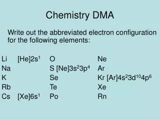
DMA and DSP
360 likes | 539 Views
DMA and DSP. Michael Urman University of Illinois at Urbana-Champaign. Introduction. Hardware to help the CPU The CPU is in control But other hardware can do the repetitive work. Agenda. Direct Memory Access (DMA) Digital Signal Processing (DSP). Overview of DMA.

DMA and DSP
E N D
Presentation Transcript
DMA and DSP Michael Urman University of Illinois at Urbana-Champaign ECE 291
Introduction • Hardware to help the CPU • The CPU is in control • But other hardware can do the repetitive work ECE 291
Agenda • Direct Memory Access (DMA) • Digital Signal Processing (DSP) ECE 291
Overview of DMA • DMA transfers large blocks of data • Reading sectors from Harddrives • Writing PCM data to the DSP ECE 291
Reading Memory • CPU executes: mov eax, [ds:esi] • Provides address • Requests data • Waits • Minimum of one bus clock cycle • Memory returns data CPU Memory ECE 291
Writing to a Device • CPU executes: out dx, al • Data transfers across the ISA bus • 1 to 4 bus clock cycles • Transfer complete CPU ISA Bus ECE 291
Waiting Is Slow • A 300MHz CPU on a 66MHz bus • 4.5 CPU cycles per bus cycle • 5 CPU cycles reading • 5 CPU cycles writing • Wastes 8 cycles, or 80% ECE 291
Direct Memory Access • CPU programs DMA and device • CPU releases data bus • DMA transfers data CPU Memory DMA ISA Bus ECE 291
CPU DMA Interaction • Master DMA asserts HOLD • CPU acknowledges with HLDA ECE 291
DMA Transfer Modes • DMA has four modes • Single • Block • Demand • Cascade • And two options for each mode • Single cycle • Auto-initialized ECE 291
DMA Transfer Modes (cont) • Master DMAC does 16bit transfers • Slave DMAC does 8bit transfers • Minimum of 1 byte • Maximum of 64KB * transfer size • DMA can sustain max 4.166MB/s • Contrast to 2.77MB/s with PIO • 16bit 44KHz PCM data requires 88KB/s ECE 291
Offset Segment Linear Address Page Offset 7 3 0 15 0 DMA Page Register • DMA addresses memory by Page:Offset • 16 64KB pages • All below 1MB • Transfer buffer cannot cross page boundary • Allocating such memory can be difficult • See Appendix A for RM DMA code ECE 291
Summary of DMA • DMA can transfer large blocks of data • From memory to device • Or from device to memory • Saves CPU time when accessing • Hard drives • Floppy drives • Soundcards ECE 291
10 4 Overview of the DSP • Soundcards come in ISA, PCI, and onboard formats • They play and record PCM sounds ECE 291
Interface to the DSP • By default, the 16bit DSP has • I/O Base 0220h • IRQ 5 • DRQ 1 • DRQ 5 • Held in BLASTER environment variable • A220 I5 D1 H5 ECE 291
Interface to the DSP (cont) • I/O port registers ECE 291
Programming the DSP • Step 1: Reset the DSP • Step 2: Set timing constant • Step 3: Program a DMA transfer ECE 291
Reset the DSP • Verifies the DSP is installed • Returns DSP to known state • Sequence (see Appendix B for code) • Write 1 to Reset port, and wait • Write 0 to Reset port, and wait longer • Verify data is available • Read data and verify reset code ECE 291
Set the Timing Constant • Controls playback and recording speed • TC = 256–1,000,000/Frequency • 165 for 11KHz • 242 for 44KHz • Sequence • Write 040h to the write port, wait • Write TC to write port ECE 291
SB16 Uses Sample Rate • Sequence • Write 041h to the base port, wait • Write the high byte of the rate • Write the low byte of the rate • E.G., 41h, 56h, 22h for 22050Hz • (5622h = 22050) ECE 291
Program a DMA Transfer • Take the load off the CPU • Support simultaneous Play and Record • Requires capable sound card • And twice as many DMA channels • Requires a known block of DMA addressable memory ECE 291
Program a DMA Transfer • Sequence (see Appendix C for code) • Program the DMA • Install an ISR on the SB Interrupt • Triggered whenever the DSP finishes an operation • Program DSP with DMA mode • Program DSP with sound format • Program data length of operation ECE 291
FM Synthesizer (MIDI) • Allows digital synthesis of prerecorded voices • Generally low quality, and never human voice • See the sound lecture for details • Use MidPak for final projects (?) ECE 291
Left Right Hardware Mixer • The mixer allows balancing ECE 291
Pmodelib: DMA.asm SB16.asm • Contain functions to do the dirty work • No more IN/OUTs • Use functions like DMA_Start, SB16_Start to play (or record) sounds • See sequence in Appendix D • Leaves you free to do mixing ECE 291
Audio Mixing • Two sound streams • One speaker • Average each sample together • MMX • Watch out for degenerate edge cases • Lowers sound quality • Bad for 8bit; not so bad for 16bit ECE 291
Caveat: No Sound Blaster • Our lab is running Windows 2000 • And some non SB compatible card • Our (current) answer: VDMSound • Emulates a 16-bit SoundBlaster • Allows us to program sound under Win2k ECE 291
VDMSound • Using VDMSound • V:\> set BLASTER=A220 I5 D1 H5 • V:\utils\Vdms2> dosdrv • Refer to PModeLib source and examples • V:\pmodelib\src\sb16.asm • V:\pmodelib\examples\testsb16.asm • Creative’s reference (C code) • V:\utils\SoundBlaster Development\Samples\ ECE 291
Summary of DSP • The DSP uses DMA for low-overhead playback or recording of PCM sound • Sound is a very popular feature in ECE291 final projects • Protected Mode vs. Real Mode? ECE 291
More Information • Sound Blaster lecture • DMA lecture • SoundLib – Real mode library • VDMSound – SoundBlaster emulation • http://ntvdm.cjb.net/ – VDMSound Homepage ECE 291
Appendix A: DMA Code ; Note: this code should be treated as pseudocode ; Code to convert segment:offset to page:page_offset ; ; SI contains offset, ; DX contains segment : mov ax,dx mov cl, 4 shl ax, cl ; shift segment left 4 shr dx, cl ; shift segment right 12 add si, ax ; add shifted segment to offset adc dh, 0 ; Now SI contains the offset within the page, ; the low 4-bits of DH contain the page # ; Disable the DMA channel so we can set it mov ax, [channel] and ax, 3 ; channel mod 4 or ax, MODE ; set mode bits out MASKREG, al ; write DMA mode ; Clear byte ptr F/F out BYTEREG, al ; any value to reset ; write mode to mode register mov al, mode out MODEREG, al ECE 291
Appendix A (cont) ; write page offset to address reg. mov ax, si ; get offset in ax out ADDRREG, al ; write LSB of DMA offset mov al, ah out ADDRREG, al ; write MSB of DMA offset ; write length (-1) to count reg. mov ax, length ; ax=length-1 dec ax out COUNTREG, al ; write LSB of size mov al, ah out COUNTREG, al ; write MSB of size ; write page# to page register mov al, dh out PAGEREG, al ; write page ; re-enable the channel mov ax, [channel] and al, 3 ; channel mod 4 out MASKREG, al ; enable sound card DMA ; now set up the target device... ECE 291
Appendix B: DSP Reset ; Note: this code is in real mode, not protected ; Reset SoundBlaster ; return value (AL): ; 0 - reset unsuccessful, wrong port?/no card found? ; AA - card found and reset successfully ; dsp_reset mov dx, [sb_addr] add dx, RESET mov al, 1 ; send 1 to reset reg. out dx, al mov dx, [sb_addr] add dx, AVAIL-RESET mov cx, 8 .burn1: in al, dx ;wait 3 us loop .burn1 mov dx, [sb_addr] add dx, RESET mov al, 0 ; send 0 to reset out dx, al ECE 291
Appendix B (cont) mov dx, [sb_addr] add dx, AVAIL-RESET mov cx, 400 .burn2: in al, dx ;wait 100+ us loop .burn2 in al, dx test al, 80h ; test data available mov al, 0 jz .rstdn mov dx, [sb_addr] add dx, READ in al, dx .rstdn: ret ECE 291
Appendix C: DMA DSP (generic ISR for transfer) ; Generic Real Mode ISR to acknowledge sound interrupt to PIC dsp_irqdone push ax push dx mov dx, cs:[sb_addr] ; sb_addr is port address add dx, AVAIL ; AVAIL=0Eh, data available port cmp byte cs:[dma_type],8 je .ack add dx, INT16-AVAIL ; INT16=0Fh, 16-bit acknowledge(SB16 only) .ack: in al, dx ; ack interrupt for DSP with dummy read mov al, 20h out 20h, al ; write EOI to 8259A cmp byte cs:[sb_irq], 8 ; do we need to ack slave PIC? (IRQ>7) jb .idone out 0A0h, al ; write EOI to 8259B .idone: pop dx pop ax iret ECE 291
Appendix D: Pmodelib Support • Initialization • DMA_Alloc_Mem (int Size, short*Sel, long *Address) • DMA_Lock_Mem () • SB16_Init (void(*)() Callback) • SB16_GetChannel () • SB16_SetFormat (int Bits, int Rate, bool Stereo) • SB16_SetMixers (long Master, long Wav, … (4 more) ) • DMA_Start (int Channel, long Address, long Size, bool AutoInit, bool Write) • SB16_Start (long size, bool AutoInit, bool Write) • SB16_Stop () • DMA_Stop (int Channel) • SB16_Exit () ECE 291