Download
1 / 38
380 likes | 512 Views
This document presents a comprehensive overview of the Energy Recovery Linac (ERL) research and development efforts aimed at creating a coherent X-ray source. It includes an introduction to the motivations behind ERL projects, outlines key technological challenges faced, and discusses various alternative design ideas. The document reflects collective insights from the Cornell University team and the broader international ERL community on the progress made, future outlook, and remarkable scientific opportunities enabled by advancements in ERL technology.

E N D
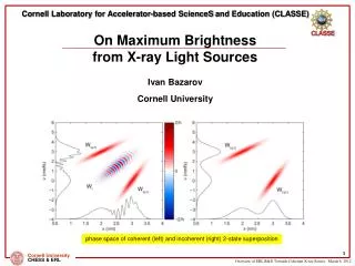
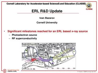
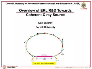
Overview of ERL R&D Towards Coherent X-ray Source Ivan Bazarov Cornell University Cornell Laboratory for Accelerator-based ScienceS and Education (CLASSE) ERL x-ray light source concept
Matthias Liepe for SRF slides; Georg Hoffstaetter for slides from his ERL’11 talk – and by proxy to the entire international ERL community Cornell team: D. H. Bilderback, M. G. Billing, J. D. Brock, B. W. Buckley, S. S. Chapman, E. P. Chojnacki, Z. A. Conway, J. A. Crittenden, D. Dale, J. A. Dobbins, B. M. Dunham, R. D. Ehrlich, M. P. Ehrlichman, K. D. Finkelstein, E. Fontes, M. J. Forster, S. W. Gray, S. Greenwald, S. M. Gruner, C. Gulliford, D. L. Hartill, R. G. Helmke, G. H. Hoffstaetter, A. Kazimirov, R. P. Kaplan, S. S. Karkare, V. O. Kostroun, F. A. Laham, Y. H. Lau, Y. Li, X. Liu, M. U. Liepe, F. Loehl, L. Cultrera, C. E. Mayes, J. M. Maxson, A. A. Mikhailichenko, D. Ouzounov, H. S. Padamsee, S. B. Peck, M. A. Pfeifer, S. E. Posen, P. G. Quigley, P. Revesz, D. H. Rice, D. C. Sagan, J. O. Sears, V. D. Shemelin, D. M. Smilgies, E. N. Smith, K. W. Smolenski, A. B. Temnykh, M. Tigner, N. R. A. Valles, V. G. Veshcherevich, Z. Wang, A. R. Woll, Y. Xie, Z. Zhao NSF DMR-0807731 for ERL R&D support at Cornell Acknowledgements
Introduction & motivation Main technological challenges Alternative ideas Outlook Outline
1986: Stanford SCA T. Smith et al. NIM A 259 (1987) 1 2004: ERL-P 1999: JLAB DEMO-FEL 1990: S-DALINAC (Darmstadt) ERL development timeline KEK, BESSY, China 2010 2000 1990 2004: BNL R&D ERL 1965: M. Tigner NuovoCimento 37 (1965) 1228 2005: Cornell gets $ 1980 1998: BINP FEL 1970 2002: JAEI FEL 2004: JLAB FEL Upgrade 1960
Geoff Krafft and Dave Douglas talk about ERL-based X-ray light source around that time (slightly earlier); MARS proposal by Gennady Kulipanov et al. (1998) Cornell ERL white paper (2000) http://erl.chess.cornell.edu/papers/2000/ERLPub00_1.pdf discusses 10^23 brightness (s.u.) out of an ERL
Progress in ERLs for Light Sources XDL’11 workshops – exciting science enabled by X-ray ERLs XDM Tickle-Probe CDI SAXS/WAXS @ sub-ps IXS
Progress in ERLs for Light Sources Operations at JLAB
Progress in ERLs for Light Sources Operations at JLAB, Daresbury,
Progress in ERLs for Light Sources Operations at JLAB, Daresbury, BINP
Progress in ERLs for Light Sources Operations at JLAB, Daresbury, BINP Designs at Cornell
Progress in ERLs for Light Sources Operations at JLAB, Daresbury, BINP Designs at Cornell, KEK/JAEA 7GeV Double Acc. XFEL-O Second Phase 3GeV ERL First Stage 11
Progress in ERLs for Light Sources Operations at JLAB, Daresbury, BINP Designs at Cornell, KEK/JAEA, BAPS 7GeV Double Acc. XFEL-O Second Phase 3GeV ERL First Stage 12
Progress in ERLs for Light Sources Operations at JLAB, Daresbury, BINP Designs at Cornell, KEK/JAEA, BAPS Test loops at KEK 7GeV Double Acc. XFEL-O Second Phase 3GeV ERL First Stage 13
Progress in ERLs for Light Sources Projects, projects, projects … progress Envisioned, developed, Operations at JLAB, Daresbury, BINP Designs at Cornell, KEK/JAEA, BAPS Test loops at KEK, HZB 7GeV Double Acc. XFEL-O Second Phase 3GeV ERL First Stage 14
Progress in ERLs for Light Sources Projects, projects, projects … progress Envisioned, developed, operational Operations at JLAB, Daresbury, BINP Designs at Cornell, KEK/JAEA, BAPS Test loops at KEK, HZB, IHEP 7GeV Double Acc. XFEL-O Second Phase 3GeV ERL First Stage 15
Energy Recovery Installations:Successful tests for ERL beam dynamics, controls, and technology • ALICE, 21MeV, 20pC • Demonstrated 9 mA CW at 150 MeV, 14kW (Jlab FEL) • VUV loop: Lasing at 10eV, achieved 2010 • Other achieved Energy Recovery • Demonstrated 9 mA CW two-pass at 30 MeV (BINP) • Demonstrated 70 µA CW at 1 GeV (JLab CEBAF) • Demonstrated 2.3kW FEL, 17MeV (JAEA)
New test installationsDouble Loop Compact ERL (KEK) • Why did we choose a double loop circulator? It is for saving construction area number of accelerator cavities running cost of the refrigerators Main parameters Layout of double loop Compact ERL
BESSY II New test installationsBNL, KEK, BESSY, and IHEP IHEP Compact TF-- 35 MeV-10 mA BERLinPro: ERL demonstration facility Cryogenic plant BESSY II BNL ERL test for coherent e-cooling of RHIC
ERL X-ray source R&D • Essentials • SRF (high Q0 , QL for low operation cost; HOM damping for > 100mA; cost-efficient cryomodule design & fabrication) • Photoinjector (demonstrate high current, longevity, brightness) • Generic facility strawman (undulators, magnets, power budget, cryoplant) • And beyond • Multi-turn designs (depends on how cheap/efficient SRF can be made) • Marry XFEL solutions (simultaneous low rep rate beam operation with high current – e.g. KEK design)
First beam from new SRF electron sources (HZB/JLAB for ERLs; Niowave/NPS; more coming up) More new guns (DC, NCRF, and SRF) with ~100mA in mind either being commissioned or under construction Cornell photoinjector highlights (over the last year): Maximum average current of 50 mAfrom a photoinjector demonstrated (Feb 2012) Demonstrated feasibility of high current operation (~ kiloCoulomb extracted with no noticeable QE at the laser spot) Original emittance spec achieved: now getting x1.8 the thermal emittance values, close to simulations (Sept 2011) Beam brightness @5GeV same as 100 mA 0.5x0.005nm-rad SR Significant photoinjector developments
Boeing/LANL RF gun tribute • New current record is 52 mA at Cornell • beats Dave Dowell’s 32 mA record of 20 years! • More in my photoinjector overview talk Cornell photoinjector: 52 mA (Feb 9, 2012)
courtesy M. Liepe Main Linac Cavity Development and high Q0 Specs: Support ERL operation with >100 mA; must minimize cryogenic wall losses (Q~21010 at 1.8 K) • Completed : • RF design • Mechanical design • Cavity fabrication • Vertical cavity RF test • Horizontal cavity test in cryomodule • Meets ERL specs: 16 MV/m, Q0 ~21010
courtesy M. Liepe RF Optimization for >100 mA ERL Operation (I) • Cell shape optimization: • ~20 free parameters • Full Higher-Order Mode characterization (1000’s of eigenmodes) • Verification of robustness of cavity design IBBU ~ 1/(worst BBU-parameter) Franklin Cray XT4 • Dipole mode damping calculated up to 10 GHz with realistic RF absorbers • Worst mode limits beam current!
courtesy M. Liepe RF Optimization for >100 mA ERL Operation (II) Optimize Cavity W.R.T. BBU parameter Introduce realistic shape variations (400 cavities) Compute dipole HOMs to 10 GHz (1692 modes /cavity) Generate realistic ERL (x100) Compute BBU current ± 0.125 mm error ± 0.250 mm error Key: simulate realistic linac ± 1.000 mm error ± 0.500 mm error Optimized cavity shape robust up to 0.25 mm shape imperfections!
courtesy M. Liepe RF Optimization for >100 mA ERL Operation (III) Results of Beam-Break-Up simulations: Note: includes realistic fabrication errors and HOM damping materials! 0.5mm 0.25mm 0.125mm 1mm Optimized cavity with 0.25 mm shape imperfections supports ERL beam currents well above 100 mA! Some of this work is summarized in N. Valles & M. Liepe, PAC’11, TUP064, p. 937
courtesy M. Liepe Mechanical Design forefficient Cavity Operation • Small bandwidth cavity vulnerable cavity microphonics (frequency modulation), especially by helium pressure fluctuations • Diameter of cavity stiffening rings used as free parameter to reduce df/dp • ANSYS simulations: large diameter rings and no rings at all have smallest df/dp • Build two prototype cavities (with and without rings) to explore both options Model of Cornell ERL Main Linac Cavity No Rings ID of rings as Fraction of Iris-Equator Distance Stiffening rings can vary from ID at iris to OD at equator Cavity optimized! No Rings S. Posen & M. Liepe, PRST-AB 15 (2012) 022002
courtesy M. Liepe Prototype Cavity Fabrication Electron Beam Welding Finished main linac cavity with very tight (±0.25 mm) shape precision important for supporting high currents (avoid risk of trapped HOMs!) Quality control: CMM and frequency check
courtesy M. Liepe Vertical Performance Test of Prototype Cavity • Cavity surface was prepared for high Q0 while keeping it as simple as possible: bulk BCP, 650C outgassing, final BCP, 120C bake Vertical cavity test results at 1.6K and 1.8K ERL main linac spec Cavity meets ERL gradient and Q0 specifications in its first test! The achievement of high Q is relevant not only to Cornell's ERL but also to Project-X at Fermilab, to the Next Generation Light Source, to Electron-Ion colliders, spallation-neutron sources, and accelerator-driven nuclear reactors.
courtesy M. Liepe HGRP 80K shield One-Cavity ERL Main Linac Test Cryomodule cavity HOM load HOM load Gate valve • Assembled and currently under testing at Cornell: • First full main linac system test • Focus on cavity performance and cryogenic performance
courtesy M. Liepe Preliminary Test Results of First ERL Main Linac Cavity in Test Cryomodule Cryomodule cavity test results at 1.8K Q0 Administrative limit. Cavity can go to higher fields Cavity exceeds ERL gradient and Q0 specifications in its first cryomodule test!
Alternative & developing ideas MARS by G. Kulipanov et al. • MARS • Trade off current for higher undulator N~104, use many passes • Much reduced injector requirements can use lower gradient linac • Becomes less appealing as injector & SRF performance/efficiency improves • Moderate number, e.g. two-pass, approaches • Several labs pursuing, capital and operational cost savings • Full energy CW linac is a nice investment if can afford • Extend ERL’s to x-ray free electron laser techniques • Not appealing for GHz rep. rates; instead use simultaneous operation with a lower rep rate beam
Simultaneous operation with high current at e.g. XFELO specs Keep additional (unrecovered) RF load ~1-2kW per SRF cavity When to use energy recovery Rep. rate Beam power @ 5GeV 100pC @ 100MHz 50MW 100pC @ 10MHz 5MW 100pC @ 1MHz 0.5MW 100pC @ 0.1MHz 0.05MW Absolutely Maybe No
BC1 BC2 Simultaneous short pulses for XFEL and generic ERL running from Cornell ERL Science Workshops, June 2006 • Initial analysis to meet XFELO specs shows it’s doable using non-energy recovered beamline <0.5 MW dump <100 A source 80 m long undulator or ID farm 100pC@1MHz or less 500 MeV 5 GeV 3rd harmonic linearizer 100 mA source
KEK plans for ERL with XFELO Others to follow? • Narrower and less divergent e-beams • More mono-energetic e-beams all of the above • Shorter pulses 3 GeVERL with XFEL-O at KEK 7GeV Double Acc. XFEL-O Second Phase 3GeV ERL First Stage
Summary & Outlook • Based on demonstrated source performance: if a hard X-ray ERL were to be built today, it would already be the brightest quasi-CW source of x-rays • There is a long list of technical issues still requiring attention, but also great progress over the last 2 years • Further light source evolution calls for free-electron laser techniques married to ERLs (or rather its CW linac at a reduced bunch rep rate) to enhance brightness and better control coherence
Advantages of ERL beamsfor light sources • ERLs have advanced, science enabling capabilities: • Large currents for Linac quality beams • Continuous beams with flexible bunch structure • Small emittances for round beams • [similar transverse properties have recently been proposed for 3km long rings] • Openness to future improvements • [today’s rings can also be improved, improvements beyond ring performances mentioned under c) may be harder to imagine] • Small energy spread (2.e-4 rather than conventional 1.e-3) • Variable Optics • Short bunches, synchronized and simultaneous with small emittances • Thus : many advantages beyond increased spectral brightness ! The breadth of science and technology enabled is consequently very large and the ERL will be a resource for a very broad scientific community. X-ray ERLs are at the beginning of a development sequence, and extensions can be envisioned, e.g. XFEL-O.
Advantages of ERL beams:Variable electron optics • Beam size vs. divergence can be optimized on each undulator straight section, without limitations by dynamic apertures. • APS: one set of beta functions • ESRF: two sets of beta functions (hi, low) • ERL: all choices are possible, not “one size fits all” • 2) Move position of minimum electron beam waist along straight section by changing quadrupole settings, without moving components, e.g. move apparent x-ray source point to compensate for changes in focal length on refractive lenses and zone plates, or move x-ray focus to the sample. • 3) There may be other New Features (e.g. optimizing flux through a collimator, monochromator because of extra free knobs) that can be developed because x-ray ERLs are at the start of development.